16 Bit Microcontroller Articles:
 8096 Memory Space : The addressable memory space on the 8096 Memory Space consists of 64 K bytes, most of which is available to the user for program or data memory. Locations which have special purposes are 0000H through 00FFH and 1FFEH through 2080H. 16 Bit Microcontroller (Read More)
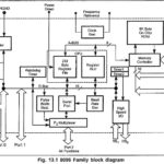 8096 Microcontroller Architecture Block Diagram : Fig. 13.1 shows the internal block diagram of 8096 Microcontroller Architecture Block Diagram. It consists of several functional units, namely CPU with 232 byte register file and register ALU 8-Kbyte internal ROM Programmable high speed I/O unit. Two 16-bit Timers/Counters Serial port Pulse width (Read More)
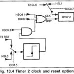 8096 Microprocessor Functional Units : Table 13.2 shows the list of major I/O functions provided by various 8096 Microprocessor Functional Units. Timers: The 8096 Microprocessor Functional Units has two 16 bit timers. The first is designated as “Timer 1” and, the second, as “Timer 2”. Timer 1 is used to synchronize events to real (Read More)
Features of 8096 Microcontroller : Before we seen the architecture, I/O pins, counter/Timers, serial data I/O, interrupts and basic assembly language programming of a 8051/8031, an 8-bit microcontroller. Here we introduce the 16-bit microcontroller MCS 8096. It is designed for high speed/high performance control applications. The Features of 8096 Microcontroller are namely, 1.The (Read More)
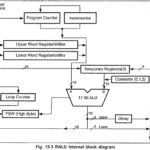 Intel 8096 CPU Structure : The major components of the CPU on the 8096BH are the register file and the register ALU (RALU). The Intel 8096 CPU Structure consists of a 16-bit ALU. It operates on a 256 byte register file instead of an accumulator. 16 Bit Microcontroller (Read More)
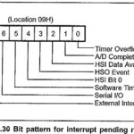 Interrupt Structure of 8096 : Eight interrupt sources are available on the Interrupt Structure of 8096. When enabled, an interrupt occurring on any of these sources will read the address of interrupt service routine (ISR) from the corresponding vector location and force a call to ISR. Table 13.9 shows the (Read More)