2 Pole Elementary DC Machine:
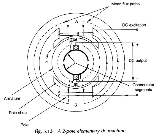
Figure 5.13 shows a 2 Pole Elementary DC Machine with a single coil rotating armature. It may be seen that the field winding is stationary with salient poles whose pole-shoes occupy a major part of the pole-pitch. An alternating emf is induced in the coil due to rotation of the armature past the stator (field) poles. The two ends of the armature coil are connected to two conducting (copper) segments which cover slightly less than a semicircular arc. These segments are insulated from each other and from the shaft on which they are mounted. This arrangement is called the commutator.
Current is collected from the commutator segments by means of carbon brushes. The connections of the coil to the outside circuit reverse each half cycle in such a manner that the polarity of one brush is always positive and the other negative. This indeed is the rectification action of the commutator-brush arrangement.
As already stated, it is because of this requirement of the mechanical rectification action, to obtain direct voltage from the alternating induced emf, that the armature in a 2 Pole DC Machine must always be a rotor and the field winding must always be placed on the stator.
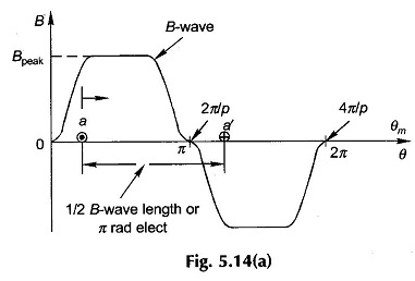
The air-gap under the 2 Pole DC Machine is almost uniform and further the pole shoes are wider than in a synchronous machine (pole-arc is about 70% of the pole-pitch). As a result, the flux density in air around the armature periphery is a flat-topped wave as shown in Fig. 5.14(a).
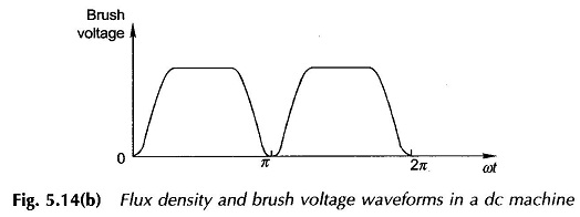
The voltage induced in the coil (full-pitched) has a similar wave shape. However, at the brushes both half cycles of voltage wave are positive, (Fig. 5.14(b)) because of the commutator’s rectification action. It is easy to see that such a waveform has a higher average value for a given value of Bpeak, which therefore explains why a dc machine is designed to have a flat-topped B-wave.
The actual dc machine armature has several coils which are connected in the form of a lap or wave winding.


