Inverting Amplifier using Op Amp:
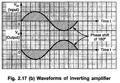
Inverting Amplifier using Op Amp – As the name suggests the output of such an amplifier is inverted as compared to the input signal. The inverted output signal means having a phase shift of 180° as compared to the input signal.
So, an amplifier which provides a phase shift of 180° between input and output is called inverting amplifier.
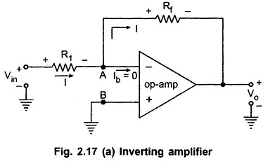
The basic circuit diagram of an Inverting Amplifier using operational amplifier is shown in the Fig. 2.17 (a).
Let us derive the expression for its closed loop gain which is Vo/Vin.
As node B is grounded, node A is also at ground potential, from the concept of virtual ground, so VA = 0
Now from the output side, considering the direction of current I we can write,
Entire current I passes through Rf as op-amp input current is zero.
Equating (1) and (2) we get,
The Rf/R1 is the gain of the amplifier while negative sign indicates that the polarity of output is opposite to that of input. Hence it is called Inverting Amplifier. The input and output waveforms are shown in the Fig. 2.17 (b).


