ZBUS Formulation:
ZBUS Formulation is given by
By Inventing YBUS
The sparsity of YBUS may be retained by using an efficient inversion technique and nodal impedance matrix can then be calculated directly from the factorized admittance matrix.
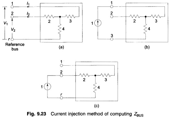
Current Injection Method:
Equation (9.33) can be written in the expanded form
It immediately follows from Eq. (9.34) that
Also Zij = Zji; (ZBUS Formulation is a symmetrical matrix).
As per Eq. (9.35) if a unit current is injected at bus (node) j, while the other buses are kept open circuited, the bus voltages yield the values of the jth column of ZBUS. However, no organized computerizable techniques are possible for finding the bus voltages. The technique had utility in AC Network Analyzers where the bus voltages could be read by a voltmeter.
ZBUS Building Algorithm:
It is a step-by-step programmable technique which proceeds branch by branch. It has the advantage that any modification of the network does not require complete rebuilding of ZBUS Formulation.
Consider that ZBUS Formulation has been formulated up to a certain stage and another branch is now added. Then
Upon adding a new branch, one of the following situations is presented.
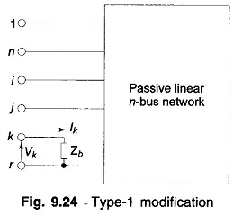
- Zb is added from a new bus to the reference bus (i.e. a new branch is added and the dimension of ZBUS goes up by one). This is type-I modification.
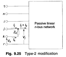
- Zb is added from a new bus to an old bus (i.e., a new branch is added and the dimension of ZBUS goes up by one). This is type-2 modification.
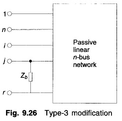
- Zb connects an old bus to the reference branch (i.e., a new loop is formed but the dimension of ZBUS does not change). This is type-3 modification.
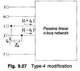
- Zb connects two old buses (i.e., new loop is formed but the dimension of ZBUS does not change). This is type-4 modification.
- Zb connects two new buses (ZBUS remains unaffected in this case). This situation can be avoided by suitable numbering of buses and from now on wards will be ignored.
Notation: i, j—old buses; r—reference bus; k—new bus.
Type-1 Modification:
Figure 9.24 shows a passive (linear) n-bus network in which branch with impedance Zb is added to the new bus k and the reference bus r. Now
Hence
Type-2 Modification:
Zb is added from new bus k to the old bus j as in Fig. 9.25. It follows from this figure that
Rearranging,
Consequently
Type–3 Modification:
Zb connects an old bus (j) to the reference bus (r) as in Fig. 9.26. This case follows from Fig. 9.25 by connecting bus k to the reference bus r, i.e. by setting Vk = 0.
Thus
Eliminate Ik in the set of equations contained in the matrix operation (9.38),
or
Now
Substituting Eq. (9.40) in Eq. (9.39)
Equation (9.37) can be written in matrix form as
Type-4 Modification:
Zb connects two old buses as in Fig. 9.27. Equations can be written as follows for all the network buses.
Similar equations follow for other buses.
The voltages of the buses i and j are, however, constrained by the equation (Fig. 9.27)
Rearranging
Collecting equations similar to Eq. (9.43) and Eq. (9.45) we can write
Eliminating Ik in Eq. (9.46) on lines similar to what was done in Type-2 modification, it follows that
With the use of four relationships Eqs (9.36), (9.37), (9.42) and (9.47) bus impedance matrix can be built by a step-by-step procedure
When the network undergoes changes, the modification procedures can be employed to revise the bus impedance matrix of the network. The opening of a line (Zij) is equivalent to adding a branch in parallel to it with impedance — Zij.


