Audio Amplifier Frequency Response:
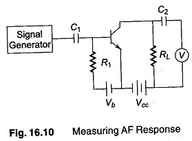
The Audio Amplifier Frequency Response is essential for filters, couplings circuits, amplifier stages and overall audio circuits. An amplifier stage is used as an example. A test setup for this amplifier stage is shown in Fig. 16.10.
This measurement is used to determine the band of frequencies that this stage can efficiently handle. Since it is an audio stage, a flat response is expected from about 50 Hz to about 20 kHz. A well designed stage may have a relatively flat response from 15 kHz to more than 50 kHz.
The signal generator is coupled to the input of the amplifier stage and the electronic voltmeter is connected across the output load resistor RL. To obtain good results, the amplifier should be in its own operational circuit. If this is not possible, the test circuit should duplicate the operational circuit as closely as possible.
The signal generator is set to a low frequency sinusoidal wave output and the amplitude is set to a reference value at a reasonable audio frequency. This amplitude is held constant as the frequency is slowly increased.
The voltmeter is set on ac and gives no indication until the signal feeds through the amplifier. As the sinusoidal wave frequency approaches the audio band, a small voltage indication appears on the voltmeter. The voltage levels off to a steady reading as the frequency reaches a value where the amplifier has the maximum response (around about 20 Hz).
The constant voltage reading holds until the frequency approaches the top of the response band. As the frequency increases above this value, the voltage slowly drops off.
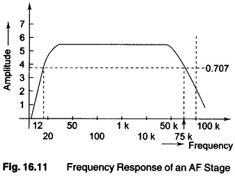
A plot of voltage and frequency, as shown in Fig. 16.11, gives the complete frequency response of this amplifier stage.
The actual response of this stage is the same as the band pass, the frequencies being between the low and high half power points that is 0.707 times the voltage. The graph in Fig. 16.11 shows a frequency response from 12 Hz to 75 kHz and the top of the curve is reasonably flat.
