Dynamic Conditions of a SystemDrive:
Dynamic or transient conditions occur in SystemDrive systems when the operating point changes from one steady state condition to another, following a change introduced in the system variables. These variables may be mechanical, such as speed, torque, etc. or electrical, such as voltage, current etc.
These conditions generally exist during starting, braking and speed reversal of the drive. The dynamic conditions arise in a variable speed drive when transition from one speed to another is required. The drive may also have transient behaviour if there are sudden changes of load, supply, voltage or frequency.
The energy storing elements in the SystemDrive, such as mechanical inertia (J) and electrical inductance (L), are responsible for the delay in response following a disturbance and for variations in transient behaviour.
The investigations of the transient behaviour or dynamic conditions of a drive are significant in the design of controllers. A knowledge of the dynamic behaviour is essential for the design of control circuits, for the correct choice of motors and for reducing losses during the starting and stopping of drives. One aims at achieving a drive which operates at optimum speed and takes the minimum possible time for settling down to the new steady-state after the initial disturbance. This is with a view to increasing the productivity of the drive. Varying parameters such as voltage, frequency and machine constants also influences the transient behaviour and a knowledge of this variation is necessary for a suitable choice of these parameters.
The dynamic behaviour of a drive has a close relation to its stability. A drive is said to be stable if it can go from one state of equilibrium to another following a disturbance in one of the parameters of the system. Stability can be identified as either steady-state or transient. The conditions of stability depend on the operating point. Stability will be discussed in detail in later sections.
Transient conditions normally exist in a motor and SystemDrive for a short interval of time. The change in thermal processes during this interval is not significant due to the large value of the thermal time constants compared to the electrical and mechanical time constants. Therefore, it can be assumed that changes in thermal conditions do not affect transient behaviour.
In drives which have infrequent starting and stopping as well as very simple control circuits, transient behaviour need not be considered.
The fundamental equation of motion giving a balance between the various torques in the drive may have to be considered while investigating the dynamic behaviour.
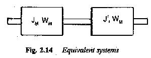
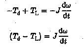
As has been stated earlier, any complex mechanical system driven by an electric motor can be simplified and represented by a single moment of inertia, friction and load, all referred to the motor shaft. A typical equivalent system is shown in Fig. 2.14. The dynamics of the drive can be investigated using the torque balance equation given by
The equation of motion considers the motor inertia Jm and the inertia of the load as seen by the shaft (J′). It also considers the friction of the motor Bm and friction of the load referred to the motor shaft (B′1). T′L is the load torque referred to the motor shaft. Considering Bω also as a part of the load torque, we can further simplify the equation
If the electromagnetic torque developed is greater than the load torque including the friction torque, the motor accelerates.![]()
If the electromagnetic torque developed is less than the load torque including friction, the motor decelerates.
This situation also occurs if Td is negative, opposing the motion, as in the case of braking. If both torque components are equal, the motor runs at constant speed.
As has been stated previously, TL comprises load torque as well as friction. The load torques occurring in mechanical systems may be passive or active. If a torque always opposes the direction of motion of the drive motor it is called a passive torque. The nature of friction is to oppose the motion, whatever be its direction. This has to be properly taken care of in writing down the equation. If the sign of drive rotation changes, these torques also change. The torques occurring due to friction, metal cutting, etc. are passive torques.
Active torques, on the other hand, oppose the motion in one direction and aid it in the other. These are associated with the potential energy of the moving parts of the system. They may therefore be either positive or negative, depending upon whether they oppose or aid the motion. The motor has to provide sufficient torque when these torques oppose the motion. In the other direction they aid the motoring torque. As an example, the potential energy of the cage of a crane or hoist is associated with an active torque. While going up it resists the motion and while coming down it aids it. Active torques retain their sign, whatever the sign of rotation in the dynamic equation.
J dω/dt is the inertial torque having a positive sign (opposes motion) during acceleration and negative sign (aids motion) during retardation. It exists only during a dynamic condition. However, the dynamic equation is determined by the signs of Td and TL.
The dynamic equation of the SystemDrive can be written based on the foregoing considerations, which may be summarised as:
- Td is positive during motoring
- TL is negative for passive torques during motoring
The sign of (Td — TL) determines the sign of dω/dt ; If (Td — TL) is positive acceleration takes place.
If the direction of rotation is reversed the equation of motion is
If TL is an active torque
In general, the equation of motion can be written as
(2.32) The sign of Td depends upon whether it is motoring (+) or braking (—). TL has a sign depending upon whether it is passive or active. Using this equation we can investigate the torque-speed of the system during dynamic conditions. The duration of dynamic behaviour can also be obtained.


