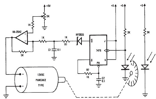
Control of DC Electric Motor:
A separately excited DC Electric Motor is very versatile as a variable speed motor. Its speed can be varied by varying the applied voltage to the armature or field current. The speed control using the variation of armature voltage can be used for constant torque application in the speed range from zero to rated speed (base speed). Speeds above base speed are obtained by means of field weakening, the armature voltage being kept at the rated value. The speed control in this case is at constant power. In both cases the speed control is smooth and stepless. However, the Control of DC Electric Motor has disadvantages as a variable speed drive, due to the presence of a mechanical commutator. The commutator actually limits the rating, highest speed of operation. It requires frequent maintenance and makes the dc motor unsuitable for application under certain environmental conditions.
With the advent of thyristors and thyristor power converters the variable voltage to the DC Electric Motor is obtained from static power converters. Phase controlled rectifiers provide variable dc voltage from constant voltage, constant frequency mains. The static apparatus is very efficient, compact and has a very good dynamic behavior. It is very easy to provide a four quadrant drive with slight modifications in the converter.
A dc chopper can be used to obtain a variable voltage from a constant dc voltage. The average value of the output voltage can be varied by varying the time ratio of The chopper.
Besides the advantages, static converter fed DC Electric Motor have a performance which is very much different from the performance of the motor operating on pure dc. The motor current has ripple content which affects the commutation capability of the motor. Additional losses are present. There may be torque pulsations. When the phase control is used the line power factor is poor.
An ac motor is a constant speed motor. Its speed depends upon the supply frequency and number of poles. The mechanical commutator is not present and therefore an ac motor has several advantages compared to a dc motor. Because of these advantages, the ac motor finds application in reactor engineering where maintenance free operation is required, in air craft drives where high power density is required, and in the textile industry where dust and explosion-proof construction is required. Ac motor drives are built for high speeds in large power ratings and due to low inertia they have a fast response. The main disadvantage of these motors was that an efficient smooth speed control in a wide range was a problem.
The problem of speed control of ac motors has been very efficiently solved with the development of thyristor power converters which can provide variable frequency, variable voltage supply. Using these converters it has been possible to achieve an ac motor having dc motor characteristics. Developments are now oriented towards replacing the dc motor by means of inverter fed ac motors with improved dynamic response.
Induction motors operating on thyristor power converters have non-sinusoidal input waveform. These cause variations in the performance, such as additional harmonic losses, torque pulsations, etc. The additional harmonic losses are responsible for increased heating and temperature rise. Consequently the motor has to be derated, particularly at low speeds. Torque pulsations at low speeds are objectionable. Hence it is necessary to modify either the motor design or the inverter, for better performance.
The speed of a slip ring induction motor can be varied by using power converters in the rotor circuit. The rotor current waveform, which is non-sinusoidal, causes variations in the performance.
Synchronous motors are also becoming popular as variable speed drives using thyristor power converters. The variable frequency for the synchronous motors is given by cycloconverters, voltage fed inverters and current fed inverters. A synchronous motor has an advantage over an induction motor. When it is overexcited it operates at leading power factor. The machine voltages can be used for commutation of the inverter. Load commutation is thus possible and consequently the power circuit becomes simple. The inverter feeding a synchronous motor can have a control from the information of rotor position. All the six thyristors of the inverter are fired (once) in a sequence by the time the rotor moves by two pole pitches (i.e., 360° el.). The motor current completes one cycle. Thus the speed and frequency are synchronized using rotor position sensing. The control is called self control. The input frequency and rotor speed are tied together. This control imparts to synchronous motor the properties of a DC Electric Motor. The problem of stability disappears and the machine has a dynamic behavior similar to that of a DC Electric Motor. A self controlled load commutated C.S.I. fed synchronous motor is now a competitor for both dc motor and induction motor.
The performance of a synchronous motor on variable frequency supply is of interest. This enables one to improve the inverter system or motor design for better performance.
