Direct Current Resistivity Method:
The specimen shape and the electrode arrangement should be such that the Direct Current Resistivity Method can be easily calculated. For a solid specimen, the preferable shape is a flat plate with plane and parallel surfaces, usually circular. The specimens are normally in the form of discs of 5 to 10 cm diameter and 3 to 12 mm thickness.
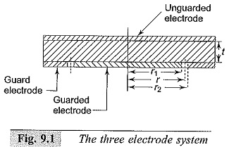
If the electrodes are arranged to be in contact with the surfaces of the specimen, the measured resistance will be usually greater due to the surface conductivity effects. Often, a three electrode arrangement shown in Fig. 9.1 is used. The electrode which completely covers the surface of the specimen is called the “unguarded” electrode and is connected to the high voltage terminal. The third electrode which surrounds the other measuring electrode is connected to a suitable terminal of the measuring circuit. The width of this “guard” electrode must be at least twice the thickness of the specimen, and the unguarded electrode must extend to the outer edge of the guard electrode. The gap between the guarded and guard electrodes should be as small as possible. The effective diameter of the guarded electrode is greater than the actual diameter and is given as follows.
Let r1, r2, and r be the radii of the guarded electrode, guard electrode including the gap, and the effective radius of the guarded electrode. Let the gap width =g and the specimen thickness = t. Then from references 5 to 6,
Electrode Materials:
For accurate measurements, the electrodes should have very good contact with the surface of the insulator specimen. Hence, it is necessary to use some type of thin metallic foil (usually of lead or aluminium of about 10 to 50 μm thickness), conducting adhesive like petroleum jelly or silicone grease. The electrodes are made simultaneously by cutting out a narrow strip by means of a compass provided with a narrow cutting edge. Sometimes conducting silver paint is also used for electrode deposition. Evaporated metal deposition on the specimen surface or use of mercury electrodes, applied by floating the specimen on a pool of mercury using confining rings with sharp edges for holding the metal, are also convenient.
Measuring Cells:
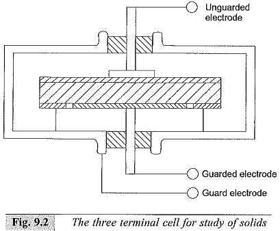
The three terminal electrode system and the measuring cell used are shown in Fig. 9.2. The measuring cell is usually a shallow metalbox provided with insulating terminals. The box itself is connected to the guard electrode and is grounded if the guard terminal is grounded. The connecting lead for the guarded electrode is taken through a shielded wire. In case the unguarded electrode is grounded, the entire box is to be placed on insulated supports and is to be placed in a grounded shield to eliminate induced voltages, and the lead from the guard electrode is doubly shielded.
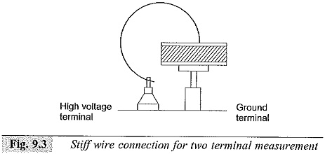
In the simple two terminal system, the measuring cell itself is the grounded support for the specimen and a small solid wire is connected to the high voltage terminal of the measuring circuit, as can be seen from Fig. 9.3. This is a simple and compact arrangement for quick measurements and requires less skill.
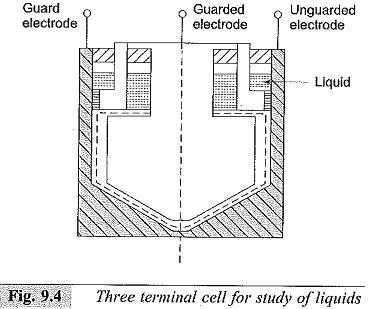
The arrangement used for the study of liquids is shown in Fig. 9.4. This consists of an outer cylindrical case and an inner cylinder with a cylindrical guard electrode. The opposing surfaces of the measuring electrodes should be carefully finished to give a polished surface, and a uniform spacing of about 0.25 mm is maintained.
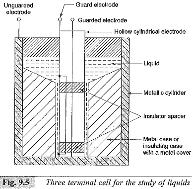
The electrode even at the highest temperatures used and should still allow easy disassembling and cleaning. Another simple arrangement of the three electrode system for the study of liquids is shown in Fig. 9.5. This consists of a metallic cylindrical container with concentric hollow cylindrical electrodes as guard and guarded electrodes. The inner surface of the container electrode (unguarded) and the outer surfaces of the guard and unguarded electrodes should be carefully finished and a clearance of about 0.25 to 0.5 mm should be accurately maintained. The arrangement requires less liquid (usually only about 1 to 2 ml).
Measuring Circuits:
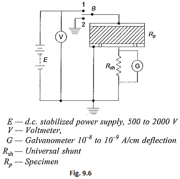
A simple measuring circuit for the measurement of resistance is shown in Fig. 9.6. The galvanometer is first calibrated by using a standard resistance of 1 to 10 MΩ (± 0.5% or ± 1%). If necessary, a standard universal shunt is used with the galvanometer. The deflection in cm per microampere of current is noted. The specimen (RP) is inserted in the circuit as shown in Fig. 9.6, and maintaining the same supply voltage, the galvanometer current is observed by adjusting the 10-9 A/cm deflection and a d.c. amplifier has to be used along with the galvanometer for higher sensitivities (up to 10-12 to 10–13 A/cm).
The resistance of the specimen is given by
where,
D = deflection in cm (with specimen), and
G = galvanometer sensitivity
in which,
n = the universal shunt ratio,
Ds = deflection in cm with the standard resistance in position,
Rs = standard resistance used for calibration, and
V = the supply voltage.
It may be noted that the deflection with the specimen in the circuit, will change with time. The initial high deflections indicate the high charging current required by the dielectric specimen. For the purpose of calculations, the steady current obtained after a considerably long changing time should only be taken. Switch B is used to discharge the specimen after the measurements are complete and as well as for the initial discharging before the measurements are undertaken.
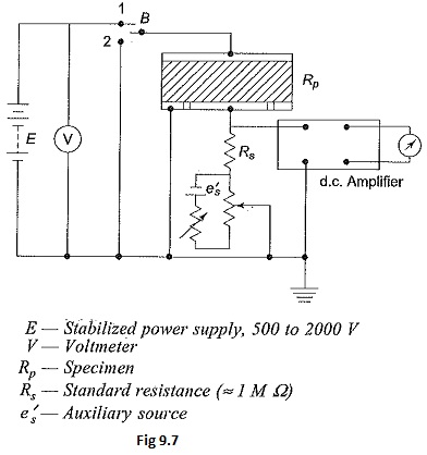
In Fig. 9.7 the d.c. galvanometer of Fig. 9.6 is replaced by a d.c. amplifier for Direct Current Resistivity Method measurements. Here, the d.c. amplifier is used as a null detector. A separate potentiometer circuit is used for obtaining a signal e equal and opposite to the voltage drop across the standard resistance Rs. At balance, the voltage drop across Rs is effectively made zero. Any a.c. voltage appearing across the standard resistance Rs is amplified only by the net gain of the amplifier which is small. Using a recording meter after the d.c. amplifier in this arrangement, the volt-ampere-time curves for long durations, of the order of several hours (day also) can be obtained. This type of information is essential to determine the relaxation time at low frequencies or with d.c.
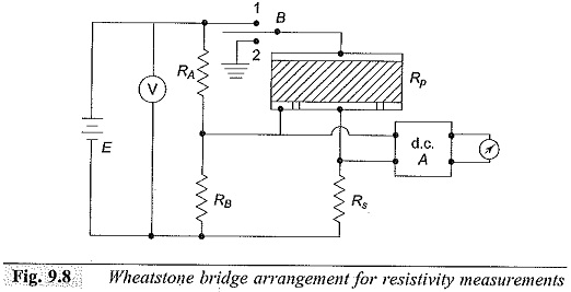
Figure 9.8 gives the Wheatstone bridge network. One of the resistances (usually RA) is made variable for balancing the bridge. At balance, RP is given by
With the specimen arrangement used, the volume resistivity ρ can be given as
where,
R = measured resistance in ohms,
t = thickness of the specimen in metres, and
r = effective radius in metres.
Using this network, the volume resistivity ρ for liquid specimens with cylindrical electrodes as shown in Fig. 9.5, can be expressed as
where,
R = measured resistance in ohms,
l = effective length of the guarded electrode in metres,
d2 = inner diameter of unguarded electrode, and
d1 = outer diameter of guarded electrode, both in metres.
Loss of Charge Method:
Using the circuit shown in Fig. 9.6, the current-time characteristic of the discharge current can be obtained by placing the switch B in position 2. The capacitance of the specimen is discharged through its own volume resistance. The slope of the current-time characteristic gives the time constant τ = CR, where C is the capacitance of the specimen.
Alternatively, a capacitance previously charged (C1) may be discharged through the specimen by inserting it in place of the battery E. By knowing the value of the capacitance C1 which is very large compared to the specimen capacitance (≈10 μF) and knowing the current-time characteristic of the discharge current, its time constant can be calculated. Hence, the resistance of the specimen is obtained from the relationship
where C1 is the capacitance used and τ is the time constant.
In the deflection method described, a limit is reached when the insulation resistance is so high that the galvanometer deflection is not at all adequate. This happens when the resistance is around 1012 Ω or more. Under these conditions, the loss of charge method is convenient. It is also convenient to measure the initial voltage V0 on the capacitor and the voltage V across it at any time τ Then the unknown resistance R can be calculated from the relationship
It is convenient to use an electrometer amplifier or electrostatic voltmeter for the measurement of the voltage. The measured value of R includes the resistance of the voltage measuring device in parallel.
The accuracy of this method depends on the accuracies with which the values of the capacitance and the voltage are measured.
