Measurement of High Voltage and Currents Articles:
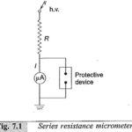
Series Resistance Microammeter: High d.c. voltages are usually measured by connecting a very high resistance (few hundreds of megaohms) in Series Resistance Microammeter as shown in Fig. 7.1. Only the current I flowing through the large calibrated resistance R is measured by … (Read More)
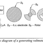
Generating Voltmeter Principle and Construction: High voltage measuring devices employ generating principle when source loading is prohibited (as with Van de Graaff generators, etc.) or when direct connection to the high voltage source is to be avoided. A Generating Voltmeter Principle … (Read More)
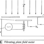
DC Electric Field Strength Meter: The DC Electric Field Strength Meter strength E can be measured by using (i) variable capacitor probe or generating voltmeter or (ii) a vibrating plate capacitor. These devices determine the electrical field intensity E by measuring … (Read More)
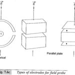
AC Field Strength Meter: AC Field Strength Meter is usually measured by introducing a small fixed capacitance probe into the field area and measuring the induced charge on it. Since the electric field between the plates of the capacitor is proportional … (Read More)
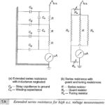
Series Impedance Voltmeter: For power frequency a.c. measurements the Series Impedance Voltmeter may be a pure resistance or a reactance. Since resistances involve power losses, often a capacitor is preferred as a series reactance. Moreover, for high resistances, the variation of … (Read More)
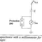
Series Capacitance Voltmeter: To avoid the drawbacks pointed out earlier, a Series Capacitance Voltmeter is used instead of a resistor for a.c. high voltage measurements. The schematic diagram is shown in Fig. 7.10. The current Ic through the meter is: where, C= capacitance of … (Read More)
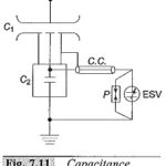
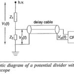
Capacitance Voltage Transformer: The errors due to harmonic voltages can be eliminated by the use of capacitive voltage dividers with an electrostatic voltmeter or a high impedance meter such as a T.V.M. If the meter is connected through a long cable, … (Read More)
Magnetic Type Potential Transformer: Magnetic Type Potential Transformer are the oldest devices for a.c, measurements. They are simple in construction and can be designed for any voltage. For very high voltages, cascading of the transformers is possible. The voltage ratio is: where … (Read More)
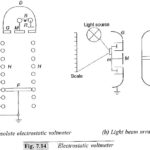
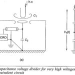
Electrostatic Voltmeters: In Electrostatic Voltmeters fields, the attractive force between the electrodes of a parallel plate capacitor is given by where, V = applied voltage between plates, C = capacitance between the plates, A = area of cross-section of the plates, d = diameter of plates s … (Read More)
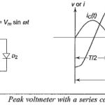
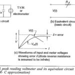
Peak Reading AC Voltmeter Circuit: When a capacitor is connected to a sinusoidal voltage source, the charging current where V is the rms value of the voltage and co is the angular frequency. If a half … (Read More)
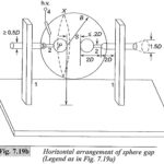
Sphere Gaps are used to measure Voltage Measurement: Sphere Gaps are used to measure Voltage Measurement – A uniform field spark gap will always have a sparkover voltage within a known tolerance under constant atmospheric conditions. Hence a spark gap can … (Read More)
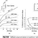
Factors Influencing the Sparkover Voltage of Sphere Gaps: Various factors that affect the sparkover voltage of a sphere gap are: nearby earthed objects, atmospheric conditions and humidity, irradiation, and polarity and rise time of voltage waveforms. 1.Effect of nearby earthed objects: The effect of nearby earthed objects … (Read More)
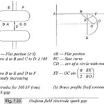
Uniform Field Electrode Gaps: Sphere gaps, although widely used for voltage measurements, have only limited range with Uniform Field Electrode Gaps. Hence, it is not possible to ensure that the sparking always takes place along the uniform field region. Rogowski presented … (Read More)
Potential Dividers for Impulse Voltage Measurements: Potential or voltage dividers for high voltage Impulse Voltage Measurements, high frequency a.c. measurements, or for fast rising transient voltage measurements are usually either resistive or capacitive or mixed element type. The low voltage arm … (Read More)
Capacitance Voltage Dividers: Capacitance voltage dividers are ideal for measurement of fast rising voltages and pulses. The capacitance ratio is independent of the frequency, if their leakage resistance is high enough to be neglected. But usually the dividers are connected to … (Read More)
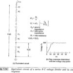
Mixed RC Potential Divider: Mixed RC Potential Divider use R-C elements in series or in parallel. One method is to connect capacitance in parallel with each R′1 element. This is successfully employed for voltage dividers of rating 2 MV and above. … (Read More)
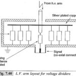
Low Voltage Arms for Voltage Divider: The mode of connection and the layout arrangement of the secondary arm of the divider is very critical for the distortion less measurement of fast transients. The L.V. … (Read More)
Peak Reading Voltmeter Circuit: Sometimes it is enough if the Peak Reading Voltmeter Circuit of an impulse voltage wave is measured; its waveshape might already be known or fixed by the source itself. This is highly useful in routine impulse testing … (Read More)
Measurement of High Direct Current: High magnitude direct currents are measured using a resistive shunt of low ohmic value. The voltage drop across the resistance is measured with a millivoltmeter. The value of the resistance varies usually between 10 μΩ and … (Read More)
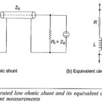
Low Ohmic Shunt: The most common method employed for high impulse current measurements is a Low Ohmic Shunt shown in Fig. 7.46. The equivalent circuit is shown in Fig. 7.46b. The current through the resistive element R produces a voltage drop … (Read More)
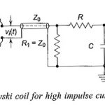
Rogowski Coil Integrator Design: If a Rogowski Coil Integrator Design is placed surrounding a current carrying conductor, the voltage signal induced in the coil is vi(t) = M dI(t)/dt where M is the mutual inductance between the conductor and the coil, … (Read More)
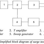
Cathode Ray Oscillograph for Impulse Measurements: Modern Cathode Ray Oscillograph for Impulse Measurements are sealed tube, hot cathode oscilloscopes with photographic arrangement for recording the waveforms. The cathode ray oscilloscope for impulse work normally has input voltage range from 5 m V/cm to … (Read More)
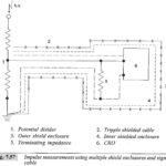
Impulse measurements using Multiple Shield Enclosures and Signal Cable: Multiple Shield Enclosures – It is essential that leads, layout, and connections from the signal sources to the CRO are to be arranged such that the induced voltages and stray pick-ups due to … (Read More)
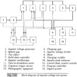
Impulse Voltage Test System: It is extremely difficult to control and adjust the Impulse Voltage Test System wave shapes for different load conditions as in the case of large capacitive loads, very low inductors or coils, transformers with high inductance and … (Read More)