Pole Changing of Induction Motor:
Pole Changing of Induction Motor – For a given frequency, the synchronous speed is inversely proportional to the number of poles. Synchronous speed, and therefore, motor speed can be changed by changing the number of poles. Provision for changing the number of poles has to be incorporated at the manufacturing stage and such machines are called, ‘pole changing motors‘ or ‘multi-speed motors‘.
Squirrel-cage rotor is not wound for any specific number of poles. It produces the same number of poles as stator winding has. Therefore, in a squirrel-cage motor, an arrangement is required only for changing the number of poles in stator. In wound-rotor motor, arrangement for changing the number of poles in rotor is also required, which complicates the machine. Therefore, this Pole Changing of Induction Motor method of speed control is only used with squirrel-cage motors.
A simple but expensive arrangement for changing the number of stator poles is to use two separate stator winding which are wound for two different pole numbers. An economical and common alternative is to use a single stator winding divided into few coil groups.
Number of poles is changed by changing the connections of these coil groups. Theoretically by dividing winding into a number of coil groups and bringing out terminals of all these groups, a number of pole numbers can be obtained by reconnecting these groups. In practice, for simplicity, winding is divided only in two coil groups. This allows the change in pole number by a factor 2. A winding arrangement for this particular case is explained as follows:
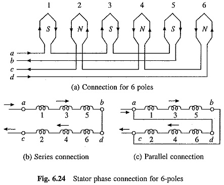
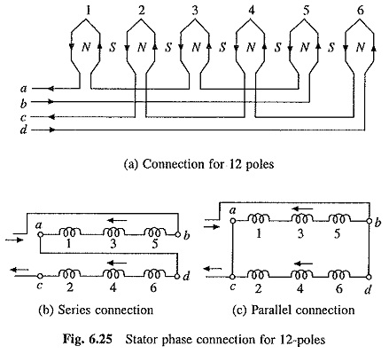
Figure 6.24(a) shows a phase winding consisting of 6 coils divided into two groups a-b consisting of odd numbered coils (1, 3, 5) connected in series and c-d of even numbered coils (2, 4, 6) connected in series. The coils can be made to carry current in the given directions by connecting coil groups either in series or parallel, shown in Figs. 6.24(b) and (c), respectively. With this connection, machine has 6-poles. If current through the coils of group a-b is reversed (Fig. 6.25(a)), then all coils will produce north poles. F
luxes coming out of these north poles will now find path through the inter-pole-spaces for going out, consequently producing south poles in inter-pole spaces. Thus, machine will now have 12-poles. Here again required direction of current through coils can be obtained by connecting the two sections a-b and c-d either in series or in parallel as shown in Fig. 6.25(b) and (c). Thus, each phase of machine winding has two coil groups, a-b and c-d, which can be connected either in series or in parallel for both pole numbers 6 and 12.
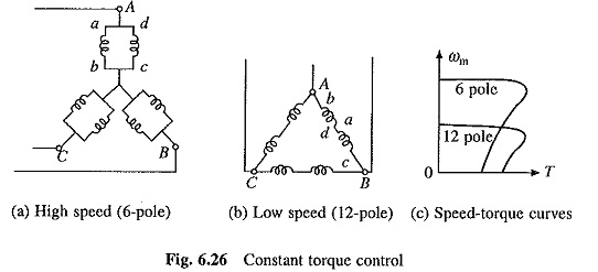
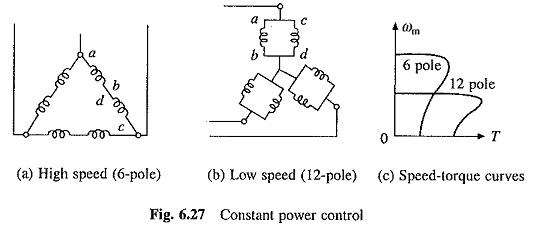
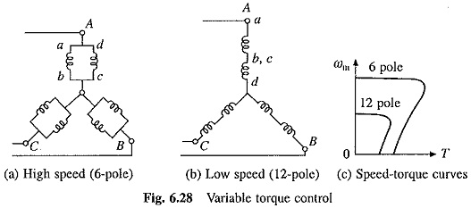
Further, three phases of machine can be connected to form a delta or star connection. By choosing a suitable combination of series or parallel connections between coil groups of each phase, and star or delta connection between the phases, speed change can be obtained with constant torque operation, constant power operation or variable torque operation. Connections and speed-torque curves for these operations are shown in Figs. 6.26 to 6.28.
