Discrete Transistor Packaging:
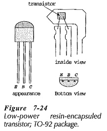
Discrete Transistor Packaging – Many low-power transistors are encapsuled in resin with protruding metal connecting leads, as illustrated in Fig. 7-24. This is known as a TO-92 package. Note the emitter, base, and collector terminal connections. These are in the sequence E,B,C, left to right, looking at the bottom of the transistor with the flat side uppermost. This kind of package is economical, but it has a limited operating temperature range.
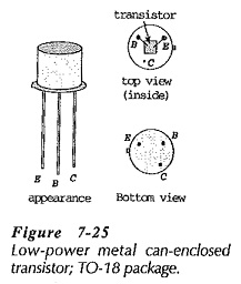
Figure 7-25 shows another method of low-power Discrete Transistor Packaging where the device is hermetically scaled in a metal can. Depending on the size of the can, this is identified as a TO-5 to TO-18 package. The transistor is first mounted with its collector in (mechanically and electrically) contact with a heat-conducting metal plate. Wires (insulated from the plate) pass through for the emitter and base connections, and the covering metal can is welded to the plate. Looking at the bottom of the transistor, and moving clockwise from the tab, the terminals are identified as E,B,C. The metal can enclosure gives a greater temperature range and greater power dissipation than resin encapsulation.
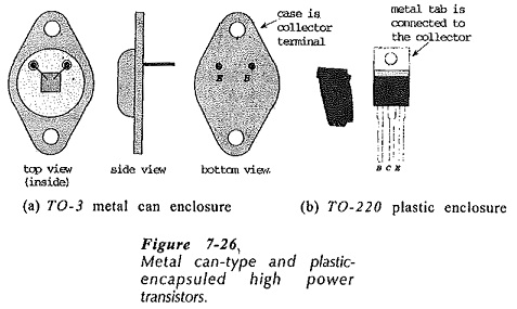
For high-power Discrete Transistor Packaging, a sealed can (TO-3) is often used, [Fig. 7-26(a)]. In this case the heat-conducting plate is much larger than in the TO-5 package, and it is designed for mounting directly on a heat sink. Connecting pins are provided for the base and the emitter, and the collector connection is made by means of the metal plate. Note the terminal identifications, again looking at the bottom of the device.
Figure 7-26(b) shows a plastic-encapsuled power transistor with a metal tab for fastening to a heat sink. Once again, note the transistor terminal identifications, and note that the the metal tab is connected to the collector. Several other package types are available for low-power and high-power devices.
IC Packages:
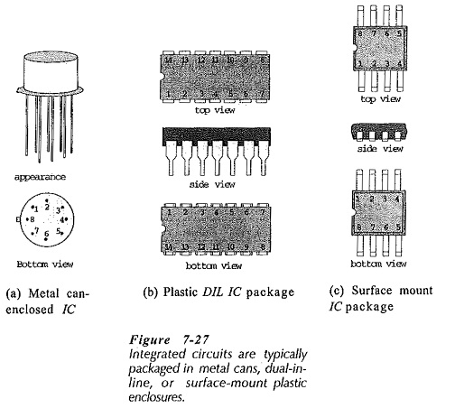
Like semiconductor devices, integrated circuits must be packaged to provide mechanical protection and terminals for electrical connection. Several standard packages in general use are illustrated in Fig. 7-27.
The metal-can-type of container affords electromagnetic shielding for the IC chip which cannot be obtained with the plastic packages, [Fig. 7-27(a)]. Note that the terminals are numbered clockwise from the tab looking at the bottom of the can.
Plastic dual-in-line (DIL) packages [Fig. 7-27(b)] are more economical than metal cans, and are widely used for industrial and consumer applications. The terminal numbering system again follows the bottom-view clockwise rule, starting from a notch in the plastic. A dimple, or other marker, is sometimes used instead of a notch. This is located on top of the package close to pin 1. DIL type packages are much more convenient for circuit board use than cans, because the lead arrangement and flat package allows greater circuit densities. The surface mounting package shown in Fig. 7-27(c) is most economical for printed circuit board use, because the terminals are soldered directly on to the board without the need for hole drilling.


