Magnetic Leakage and Fringing:
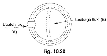
Magnetic Leakage and Fringing – Figure 10.28 shows a magnetized iron ring with a narrow air gap, and the flux which crosses the gap can be regarded as useful flux. Some of the total flux produced by the ring does not cross the air gap, but instead takes a shorter route as shown in Fig. 10.28 and is known as leakage flux.
The flux while crossing the air gap bulges outwards due to variation in reluctance. This is known as fringing. This is because the lines of force repel each other when passing through the air as a result the flux density in the air gap decreases. For the purpose of calculation it is assumed that the iron carries the whole of the total flux throughout its length.
The ratio of total flux to useful flux is called the leakage coefficient or leakage factor.
Composite Series Circuit:
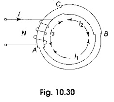
Consider a toroid composed of three different magnetic materials of different permeabilities, areas and lengths excited by a coil of N turns.
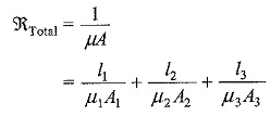
With a current of I amperes as shown in Fig. 10.30. The lengths of sections AB, BC and CA are I1, I2 and I3 respectively. Each section will have its own reluctance and permeability. Since all of them are joined in series, the total reluctance of the combined magnetic circuit is given by
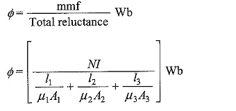
The flux produced in the circuit is given by


