Thyratron Working Principle:
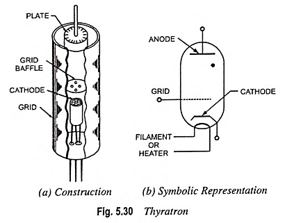
Thyratron is a hot cathode gas filled triode. Normally it is filled with a small amount of inert gas such as argon, hydrogen, neon or mercury vapour. The fast acting devices do not use mercury vapour as the mercury vapour has the disadvantage of characteristics varying with temperature and it takes time in deionization. The characteristics of hydrogen thyratron are stable and the devices are fast. Plate is disc of graphite. The special construction oxide coated cathode is used so that its surface is not damaged due to bombardment of positively charged particles. The control grid has a metal cylinder surrounding the cathode with one or more perforated discs known as grid baffles near the centre. Thus the control grid acts as an electrostatic shield between cathode and anode except for the holes in the grid baffles.
Operation of Thyratron:
Before the tube fires, its characteristics are similar to those of a vacuum triode i.e. the plate current (small in magnitude) can be varied by variation of potential applied to the grid. After firing of the tube the grid loses control over plate current completely and plate current is limited by the external resistance in the plate circuit i.e. the thyratron behaves like a diode. The introduction of grid in between the plate and cathode makes it possible to control the conditions under which the discharge should start.
On heating of the cathode of a thyratron electrons are emitted. Whether or not the electrons flow to the +ve charged plate depends upon the potential applied to the grid. Suppose the grid initially has a high negative potential while the plate has steady positive potential. The negative grid prohibits the flow of plate current. If the grid potential is gradually reduced, a point is reached when a very small thermionic plate current commences. Further reduction in grid potential causes increase in plate current and a point is reached at which the gas ionizes and enormous plate current flows. At this point, i.e. when the tube is said to have fired, a hot cathode discharge appears, plate-to-cathode voltage falls to 15 to 20 volts, the grid loses control over plate current completely and plate current is limited by external resistance in the plate circuit. The negative grid potential for a given plate potential at which the ionization starts is known as the critical grid potential. As the plate potential increases the critical grid potential is increased. If the grid potential is more negative than the critical grid potential the thyratron will not fire. And if the grid potential is lesser negative than the critical grid voltage, the thyratron will fire as soon as the plate potential is switched on.
When the thyratron fires, the gas in thyratron gets ionized having equal number of positively charged particles and the electrons. The electrons move towards the plate and increase the plate current. The positively charged particles move towards the cathode where they combine with the electrons and get neutralized. If the grid is held negative, they are gathered around the grid making a sheath of positively charged particles, the total charge of which is just sufficient to neutralize the grid potential. If now the grid is made more negative the thickness of the sheath increases and if the grid is made less negative the thickness reduces as such the flow of electrons is not controlled by the grid and thus loses control after the firing of thyratron. Now for stopping flow of current it is necessary to reduce the plate voltage below the tube striking voltage, or to open the plate circuit, for a period long enough for deionization of gas in the tube. The grid then regains control and again prevents the flow of plate current until the grid voltage is brought to its proper value.
Since the only function of the grid is to delay or prevent the starting of the current, the grid is naturally designed to achieve its purpose with as little grid voltage as possible. The grid, therefore, is quite an extensive structure. The critical grid voltage varies with the plate voltage to some extent, and also with the design of the grid.
Plate Voltage–Plate Current (or Plate) Characteristics:
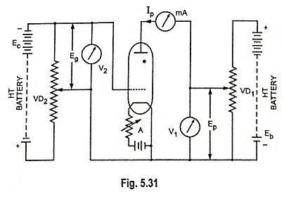
These characteristics are drawn for various grid voltages. The circuit arrangement is shown in Fig. 5.31.
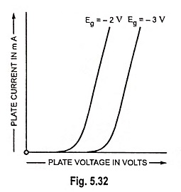
For a given grid voltage when the plate voltage is increased from zero, initially there is no plate current but when the plate voltage is further increased, a voltage is reached, called the breakdown voltage, the current at once shoots up and is limited only by the external resistance in the plate circuit. If the grid is made more negative, the tube will breakdown at higher plate voltage, as illustrated in Fig. 5.32.
Grid Control Characteristics:
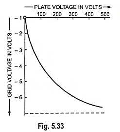
The curve drawn between plate voltage and critical grid voltage is called the grid control characteristic or starting characteristic or breakdown characteristic. This characteristic can be determined by determining the value of critical grid voltage for different values of plate voltage and plotting them, as shown in Fig. 5.33. The slope of this characteristic is known as control ratio.
Applications of Thyratron:
Thyratron has two main fields of applications :
(i) As an electronic switch to handle heavy currents and (ii) as a grid controlled rectifier when voltage control is required. The thyratron, when used as electronic switch, keeps the circuit open from the plate to cathode so long as the grid is kept at high negative potential. As soon as the grid potential is brought to such a value that the tube fires, the circuit is closed.
The thyratron switch has two great advantages over mechanical switches : (i) it is electrically operated and requires only a minute amount of energy to close it, so that it leads itself readily to automatic operation; (ii) operation is very fast. However, it has got some disadvantages also such as (i) voltage drop of 8 to 18 volts in the circuit; (ii) it cannot open dc circuit; (iii) a single thyratron will pass only the positive half waves. A second thyratron connected in parallel with the first one but with opposite polarity may be used to pass the negative half waves. A thyratron can open ac circuit, with a delay that never exceeds one half-cycle, so long as frequency is not so high that the time of one half cycle is less than the deionizing time.
The thyratron finds wide use in timing and other control applications.
The fact that its time of firing may be controlled makes the thyratron adaptable to heat control in resistance welding. By delaying or advancing the time during the cycle at which the tube fires, the average amount of welding current allowed to flow per cycle may be increased or reduced. In addition to this, the number of cycles that the welding current is allowed to flow may be controlled very accurately.
Thyratron rectifiers are also used in electronic methods of electric motor control for both small and large powers. The main advantages of electronic motor control are that the control can be made to depend on very minute signals such as those obtained from a photocell or even a thermocouple and that where necessary an extremely precise control can be obtained.
Control may be affected in several ways such as (i) with direct voltage applied to the plate as well as to the grid, (ii) with alternating voltage to the plate circuit and direct voltage to the grid and (iii) alternating voltage applied on both the grid and plate. In the first case the tube will fire and conduct whenever the grid voltage is made less negative than critical grid voltage and will again stop to conduct when the plate voltage is reduced below striking voltage or the plate circuit is opened. In the second case the grid will regain control when the plate voltage becomes negative, hence conduction will be stopped every half cycle and the tube breakdown will occur each half cycle as the plate voltage becomes positive, the point at which the tube fires depends upon the grid voltage. The average current flow can be controlled, therefore, by controlling the length of time during the half cycle that the tube is conducting i.e. by controlling the breakdown point. In the last case breakdown point is determined by the phase relation of the two voltages as well as by their magnitudes. There will thus be a point in each positive half cycle of the cathode-plate path when the tube will breakdown, if the grid voltage has a small negative value than the critical grid voltage with reference to the plate voltage, which will result in ionization and conduction. By using a phase shifting device to control the phase of grid voltage with respect to the cathode-plate voltage wave the duration of current flow may be controlled from zero to point represented by practically all the positive half cycles of plate voltage.
The thyratron cannot be employed as an amplifier like a vacuum triode because the grid voltage has no control over the magnitude of plate current after firing of the tube.


