What is Diode Resistance?
What is Diode Resistance? – As already discussed, a forward-biased diode conducts easily whereas a reverse-biased diode restrains the flow of current, so a diode has a low forward resistance as compared to high blocking or reverse resistance.
Forward Resistance. The resistance offered by a diode in the circuit, when forward biased, is known as the forward resistance. This resistance is not the same for dc as well as changing current. Thus, forward resistance is of two types viz. dc or static resistance and ac or dynamic resistance
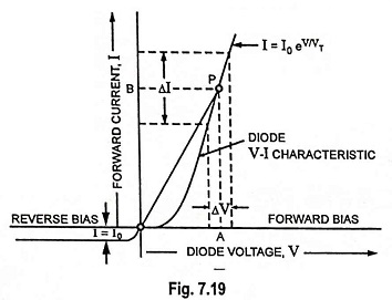
DC or static resistance, R is the resistance offered by a diode to the direct current. It is simply the ratio of the dc voltage across the diode to the direct current flowing through it. It can be determined by determining the ratio of voltage drop across the diode to the current flowing through it. At any point P on the V-I characteristic of the diode (Fig. 7.19), the voltage across the diode is OA and the corresponding current is OB.
So dc or static resistance,
Thus at any point on the V-I characteristic of the diode, the dc or static resistance R is equal to the reciprocal of the slope of the line joining the operating point to the origin.
DC or static resistance is not constant but depends on the operating point on the V-I characteristic of the diode. It is different at different points, as illustrated in Fig. 7.19. From Fig. 7.19 it is obvious that the dc resistance of a diode in the forward-bias region decreases as the region of higher voltages and currents is approached.
In the reverse-bias region, the current I = I0, constant in magnitude, the resistance of the ideal diode is essentially infinite (open-circuit equivalent).
Any way dc or static resistance does not form a useful parameter of the diode.
AC or dynamic resistance r is resistance offered by a diode to the changing forward current. It may also be defined as the reciprocal of the slope of the forward characteristic of the diode. It forms an important device parameter for small signal operation. However, it varies with the operating voltage.
From Eq. (7.20)
For a forward bias greater than a few tenths of a volt,
and according to Eq. (7.20) I ≫ I0, and dynamic resistance r is given approximately by
From above equation it is obvious that for forward bias r varies inversely with the current I. At room temperature (27°C or 300 K) VT = 0.026 V or 26 mV.
Substituting η = 1 and VT = 26 mV in above Eq. (7.32a), we have
The above equation implies that the dynamic resistance of a diode can be determined simply by substituting the quiescent value of the diode current into the equation. There is no need to have the characteristic available or to worry about sketching tangent lines as defined by Eq. (7.32c), given below.
The ac or dynamic resistance can be determined from the forward characteristic, as illustrated in Fig. 7.19.
AC or dynamic resistance,
Equation (7.32b) indicates that the incremental forward resistance of the P-N junction diode is quite low. For example, when diode current is 26 mA, the diode resistance is 1 Ω.
Actually diode ac or dynamic resistance for forward bias is slightly different from that obtained from above equation. This is because of bulk and contact resistance of the semiconductor device. This additional resistance level can be included in Eq. (7.32b), by adding a factor denoted rB as appearing in Eq. (7.32d)
For large values of forward current the first term 26mV/I(mA) giving apparent forward or junction resistance r is negligible so
r’ = rB. For small values of forward current, rB is negligible so r’ = 26mV/I(mA).
The incremental backward resistance (i.e., resistance with reverse bias), is ideally infinite because of the zero slope of the V-I characteristic in this region.
This conclusion also follows from Eq. (7.31), upon inserting I = -I0 for negative values of bias voltage. This diode resistance for reverse bias
However, the apparent backward resistance is not infinite because for any value of reverse bias there does exist a small current I0. For germanium and silicon junction diodes this resistance is quite large compared to the apparent forward resistance. In germanium diodes the ratio of apparent backward to forward resistance is 400,000 : 1 while for silicon diodes this ratio is 1,000,000: 1.


