Overhead Construction for Tramways, Trolley Buses and Railways:
As we know already that, for trams, trolley buses and for railways operating at 1,500 V and above overhead contact wire is used. The design of overhead construction for tramways, trolley buses and railway system is more complex in comparison to conductor rail system because of greater difficulty of ensuring that the collector and contact wire remain in contact at a fairly even pressure.
Tramways and Trolley Buses:
The overhead construction for tramways has to conform the following regulations:
- The trolley wire is to be erected at a minimum height of 5.185 metres above the street surface (except under bridges).
- The trolley wire is to be supported at intervals not exceeding 36.6 metres.
- Each trolley wire must be divided into sections not exceeding 0.8 km in length with an emergency switch between every two sections.
- The trolley wire should be capable of withstanding stresses due to variation in temperature.
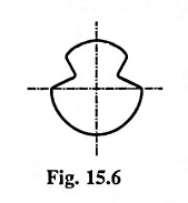
The materials employed for trolley wire are hard drawn copper or alloys of copper (cadmium copper or silicon bronze). The alloy is preferred because it has uniform hardness throughout the x-section whereas in case of hard drawn copper the hardness is confined to the outer surface i.e., the skin of the trolley wire only. The uniform hardness gives uniform wearing of conductor, which is highly desirable in electric traction. The trolley wire is usually of circular grooved cross section, as illustrated in Fig. 15.6. The cross-sectional area of a standard trolley wire is 80 mm2.
The trolley wire is supported and insulated from a transverse span wire by means of a steel bolt screwed into a gunmetal ear. The gunmetal ear is attached to the trolley wire, and the bolt is insulated from and held in a hanger attached to the span wire. The span wire is supported from poles erected facing each other on both sides of the road and insulated there from.
On straight runs the span wire is above the trolley wire but at curves the span wire is in level with trolley wire. Hangers employed for curved paths are known as ‘pull-offs’. The span wire is of stranded galvanised steel, The span wires may be extended over the whole width of the road (in which case these are attached to poles on each side of the road) or may be of a shorter length (in which case these are attached to brackets carried from horizontal arms attached to the poles at one side of the road). The former arrangement is known as span wire construction and the latter bracket arm construction.
Railways:
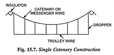
Since in railways a sliding current collector (bow or pantograph) is employed, therefore, the contact wire is required to be suspended with very small sag so that the contact between the wire and collector may be maintained at high speeds. This is achieved without excessive tension in the wire by employing spans of comparatively shorter length (3 to 4.5 metres). For such short spans an indirect method of suspension is adopted, in which the trolley wire is supported by another wire known as the “Catenary” or “Messenger” and is fixed with considerable sag (2 to 3 per cent of the span) between supports at suitable distance. The wire is usually made of more than seven strands of steel. To avoid the use of insulated droppers the whole of the messenger wire is usually insulated, and it may therefore be used if required for carrying current. The position of contact wire remains practically constant at all temperatures which may cause large amount of sag in the catenary wire. Nowadays the catenary construction employed is of either the single catenary or compound catenary.
Single Catenary Construction:
In single catenary construction, a steel wire with 7 or more strands supports the trolley wire by means of droppers clipped to catenary and trolley wire at equidistant horizontal intervals. The span of catenary wire may be from 45 to 90 metres with a sag of from 1 to 2 metres respectively for straight track. The distance of droppers is between 3 and 5 metres. On curved track the spans of shorter lengths are employed and the trolley wire is kept in position by pull-off wires. Such construction provides sufficient flexibility for speeds up to 120 kmph without any problem of current collection. Besides this it is relatively cheaper, easy to erect and does not require heavy maintenance. Single catenary construction is considered suitable for most light weight ac systems and for branch and loop lines and secondary routes where traffic density is low and operating speeds are low.
Compound Catenary Construction:
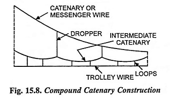
The compound catenary construction is employed for heavy current i.e., where traffic density is high. It consists of three wires, all in the same vertical plane. The upper wire is catenary wire, which is insulated from the supporting structures. From this wire another wire, known as intermediate catenary, is supported by droppers clipped to both wires. The third wire i.e., trolley wire is maintained in definite and constant tension by means of automatic tightening gear. Both contact and catenary wires are divided in sections of 150 metres and each section is anchored at the centre. The purpose of intermediate catenary besides increasing the current carrying capacity is to provide more uniformity in elasticity.


