Arc Furnace – Definition, Types, Advantages and Application:
When a high voltage is applied across an air gap, the air in the gap gets ionised under the influence of electrostatic forces and becomes conducting medium. Current flows in the form of a continuous spark, called the arc. It is to be noted that a very high voltage is required to establish an arc across an air gap but to maintain an arc small voltage may be sufficient. Alternatively an arc can also be produced by short circuiting the two electrodes momentarily and then withdrawing them back. In this method of striking an arc, high voltage is not required. Arc drawn between two electrodes produces heat and has a temperature between 1,000 °C and 3,500 °C depending on the material of the electrodes used. The use of this principle is made in electric arc furnace.
Usually arc furnaces are of cylindrical shape but recently conical shaped shells have been used. Even in conical shapes the horizontal cross section is cylindrical. The conical shape has the advantage of a large surface area per unit bath volume. It consumes less power and the radiation losses are reduced. Melting time is also reduced. Bottom, side walls and roof of the furnace are lined with firebricks, magnesite bricks and silica bricks. The bottom is lined with magnesite mix or ground ganister mix depending upon whether the basic or acidic lining is required. The electrodes project through the top or sides of the chamber and are arranged for easy replacement and adjustment. Each furnace is provided with charging door and tap hole for introducing the charge and taking out the molten metal. These doors and tap holes are also to be suitably lined. To minimize heat losses the size of the doors/tap holes and the opening time has to be reduced. The furnace rests on platform which can be titled for pouring the molten metal through the door opening in the side of the shell. Tilting mechanism consists of a motor which drives a pinion which meshes with a semicircular toothed rack at the bottom of the platform.
The furnaces may be door-charge type or the top-charge type. Large furnace installations are often equipped with side door charging. Top charging is growing in favour for medium size furnaces. In this method for charging the roof of the furnace is removed, and a complete charge is placed in the chamber by a drop bucket handled by an overhead crane. This saves labour and time.
The electrodes used in arc furnaces are of three types namely carbon electrodes, graphite electrodes and self-baking electrodes. Material of the electrodes namely carbon and graphite has been selected on account of their electrical conductivity, insolubility, infusibility, chemical inertness, mechanical strength and resistance to thermal shock. The size of these electrodes may be 18 cm to 27 cm in diameter. With graphite or carbon electrode, the temperature obtainable from the arc is between 3,000 °C and 3,500 °C. The trend is toward the general use of graphite electrodes. Carbon electrodes are used with small furnaces for manufacture of ferro-alloys, aluminium, calcium carbide, phosphorous etc. Self-baking electrodes are employed in ferro-alloys and electrochemical furnaces and in electrolytic production of aluminium. Owing to lower resistivity of graphite (one fourth that of carbon), graphite is required half in size for the same current resulting in easy replacement. Graphite begins to oxidise at about 600 °C where as carbon at about 400 °C. Under average conditions the consumption of graphite electrodes is about one half that of carbon electrodes. Electrode consumption for steel-melting furnaces varies between about 4.5 and 9 kg of electrodes per tonne of steel with carbon electrodes, and between about 2.27 and 6.8 kg for graphite electrodes. Carbon electrodes are very cheap and cost less than one half as much for same weight as graphite electrodes. The large area of carbon electrodes allow for more uniform heating. However, the arc has to be brought nearer the surface of the refractory lining and, therefore, the life of the refractory is shortened. Carbon electrodes are made of anthracite coal and coke where as graphite electrodes are obtained by heating the carbon electrodes to a very high temperature. Self-baking electrodes are made of special paste, whose composition depends upon the type of process for which it is used, contained in thin steel cylinder. The flow of current produces heat and the paste is baked and formed into an electrode.
Types of Arc Furnaces:
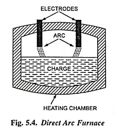
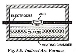
Arc furnaces are of two types namely (i) direct arc furnaces and (ii) indirect arc furnaces. In a direct arc furnace, shown in Fig. 5.4, the arc is formed between the electrodes and the charge, while in the indirect arc furnace the arc is formed between the electrodes, as shown in Fig. 5.5, and heat is transmitted to the charge solely by radiation.
1. Direct Arc Furnace:
In a direct arc furnace charge acts as one of the electrodes and the charge is heated by producing arc between the electrodes and the charge. Since in a direct arc furnace, the arc is in direct contact with the charge and heat is also produced by flow of current through the charge itself, the charge can be, therefore, heated to highest temperature. In case of a single phase arc furnace two electrodes are taken vertically downward through the roof of the furnace to the surface of the charge and in a 3-phase furnace three electrodes put at the corners of an equilateral triangle, project on the charge through the roof and three arcs are formed. The current passing through the charge develops electromagnetic field and necessary stirring action is automatically obtained by it. Thus uniform heating is obtained.
It is commonly used for production of steel. The usually size of such a furnace is between 5 and 10 tonnes, though 50 and 100 tonne arc furnaces have also been developed. The main advantage of direct arc furnace over cupola method for production of steel is that purer production is obtained and the composition can be exactly controlled during refining process. Another advantage is that arc furnace can operate on 100% steel scrap which is cheaper than pig iron where as the cupola requires a proportion of pig iron in cupola charge. This is the reason, that direct arc furnaces even being costlier in initial as well as operating costs are preferred. Though such furnace is employed both for melting and refining, but due to its higher cost it is used for refining than melting. The power factor is about 0.8 lagging. For 1 tonne furnace power required is about 200 kW and energy consumed is 1,000 kWh/tonne.
2. Submerged Arc Furnace:
These are cylindrical furnaces in which arc is formed between the carbon electrodes (from the top) and hearth electrodes. The hearth lining is of magnesite which becomes comparatively good electrical conductor when hot. It is also mixed with coke or graphite. Sometimes a conducting hearth is used as electrode. The number of electrodes, taken from the roof depends on the type of supply. One for single phase, two or four for two phase and three for three phase supply, bottom conductor being connected to the neutral. Usually 3-phase supply is used for dealing with large power, usually required. The current from the top electrode passes through the arc to the charge and returns through the electrode at the bottom of the charge. Better distributed resistance heating is obtained since charge behaves as the resistance. Similarly better mixing of charge takes place. The current under short circuit is limited due to charge, which otherwise in indirect furnace is very high. Power is controlled by varying distance between the electrodes or by varying the voltage applied to the electrodes. In a direct arc furnace the length of arc is varied for this purpose. These furnaces are used for the manufacture of ferro-alloys like ferro-chrome and ferro-manganese. The power factor is about 0.8 lagging. The stirring action is inherent due to electromagnetic forces set up by the current resulting in uniform heating of charge.
3. Indirect Arc Furnace:
In this case arc is formed between two electrodes above the charge, as shown in Fig. 5.5 and heat is transmitted to the charge solely by radiation. In this case the temperature of the charge is, therefore, lower than that in case of direct arc furnace. Since in this furnace current does not flow through the charge, there is no stirring action and the furnace is required to be rocked mechanically. That is why the furnace is made of cylindrical shape, with the electrodes projecting through the chamber from each end and along the horizontal axis. By rocking action there is thorough mixing of the charge. The life of the refractory lining also increases since the molten metal comes in contact with the lining and takes away some of its heat thus preventing it from attaining excessive temperature. The efficiency is increased because the charge is heated not only by radiation from the arc but by conduction from the heated refractory during rocking action. Its construction limits the number of electrodes to two, so single-phase supply is required. The size of the furnace is thus limited by the amount of single-phase load, which can be taken from one point. The arc is produced by bringing the electrodes into solid contact and then withdrawing them. Power input is regulated by adjusting the arc length by moving the electrodes.
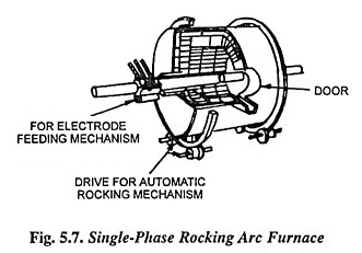
An electric motor is employed for operating suitable grinders and rollers to provide rocking action to the furnace. At start, the rocking action is carried through an angle of 15 to 20° and as the melt proceeds the angle is increased to about 200° at a frequency of about 2 cycles per minute.
Such furnaces have got following advantages :
- Low Metal Losses: Since furnace chamber is closed and a reducing atmosphere above the metal is produced due to carbon arc, therefore, metal losses due to oxidation and volatilisation are quite low.
- Economical: Melting is rapid and takes place in a completely closed chamber resulting in small heat losses and low power consumption. Higher production rate gives low labour costs resulting in lower overall production cost per tonne of molten metal.
- Sound Castings: The agitation produced by the rocking action of the furnace and the absence of combustion gases ensure products free from blow holes, inclusion and segregations. Higher pouring temperature may readily be attained. Thus sound castings in thin and intricate designs can be produced.
- Flexible: Single furnace is capable of handling small or large heat of widely differing analysis. Interchangeable furnace shells can be used for different alloys and can be substituted in a few minutes.
Due to indirect heating the furnace is suitable for comparatively low melting point. So these furnaces are used for melting non-ferrous metals. These are also used to a considerable extent in iron foundries where relatively small quantity of metal is required intermittently. The capacity of furnace varies from 0.25 tonne to 3 tonnes. The power factor is about 0.85. The energy consumption is about 275 kWh/tonne for brass: 325 kWh/tonne for bronze and 400 kWh per tonne for copper.
Even though Ajax Wyatt induction furnace is its chief rival in the field of the non-ferrous metals, owing to its higher efficiency, it is more suitable in situations where the charge has to be varied frequently or where heating is intermittent.
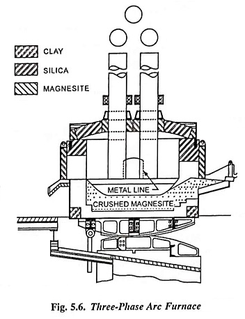
The three-phase arc furnace having a steel bowl chamber with a refractory lining is shown in Fig. 5.6. Single-phase rocking arc furnace is shown in Fig. 5.7.
Power Supply and Control
An arc furnace used for melting and refilling of steel requires power of about 500 kW per tonne for small furnaces (say for 1/2 tonne capacity) and of about 200 kW per tonne for very large furnaces (say for 50-100 tonne capacity). The energy required is usually between 600 and 800 kWh per tonne. For the arc furnaces used for refining only electrical energy consumption is about 100-120 kWh/tonne. Thus it is seen that the power consumption of the arc furnace is very high. The arc voltage lies between 50 and 150 volts, the current required to give the above mentioned power is, therefore, of the order of several hundred or thousand amperes. The reasons for employing low voltage high current power supply for arc furnaces are as follows :
- Heating effect is proportional to the square of the current, therefore, to achieve higher temperatures heavy currents are essential.
- The maximum secondary voltage is also limited to 275 V (line-to-line open-circuit voltage) because of insulation and safety considerations.
- By using low voltage and high current the electrodes are kept very near to the charge as the arc is of small length. Thus arc remains away from the roof and, therefore, life of the roof refractory is increased.
- Higher voltage causes higher voltage gradient between the electrode and the charge causing nitrogen of furnace atmosphere ionised and absorbed by the charge, which produces embrittlement.
Thus a transformer having low voltage and large current on the secondary and of a special design having mechanical rigidity to enable the windings and the electrical insulation to withstand the heavy mechanical stresses set up by the high current surges is required for the arc furnace. The transformer used with arc furnace is of oil-immersed water-cooled type. A typical specification for a 3-phase arc furnace transformer includes an extended primary winding with taps there in for the secondary voltage range 235-220-205-190-175-160 volts, with the primary winding connected in delta. This voltage range is extended by changing the connections of the primary windings from delta to star giving 58% voltage from each tap. Both core type and shell type transformers, can be used, but the latter type is preferred because it facilitates the bringing out and bracing of the heavy current leads.
It is desirable to arrange the furnace and transformer in such a way that the current leads are of shorter length. Also in order to keep inductance of these leads low they should be placed as close together as possible and they must be of such a shape as to reduce skin effect to a minimum. Since the leads from the transformer to the furnace are to carry heavy currents, so leads consisting of rectangular copper strips spaced a few mm apart are mostly employed as current carrying conductors.
The voltage-ampere characteristic of the arc is negative, i.e., with the increase in arc current, the resistance of the arc decreases, and a stabilising element (reactor) is, therefore, required for the stability. Reactor also serves as a safety device by limiting the current in the circuit when an electrode touches the charge. The inherent reactance in the circuit of a large furnace 5,000 kVA and larger may be and usually is sufficient for the purpose but the smaller installations require more or less supplemental reactance.
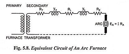
The equivalent circuit of an electric arc furnace is shown in Fig. 5.8 where RT and XT are the equivalent resistance and reactance of the furnace transformer referred to the secondary side. RL and XL are the resistance and reactance of leads. RE is the resistance of electrodes and EA = IRA, the voltage drop across the arc. The arc current depends upon the resistance and reactance of transformer (RT and XT), resistance and reactance of the leads (RL and XL), resistance of the electrodes (RE) and the arc resistance RA.
The power input can be controlled by raising or lowering the electrodes which results in variation of the arc resistances RA. The power input can be also controlled by changing the tapping of transformer which results in variation of voltage across the furnace. For complete control of furnace temperature and to achieve best operating conditions both voltage and electrode controls are employed.
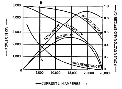
Figure 5.9 illustrates the performance characteristics of a typical arc furnace. Initially when the electrodes are touching the charge, i.e., arc resistance is zero, the current is limited by the impedance of the furnace circuit and the power input to the furnace is almost zero (copper losses in the transformer windings). Again when the electrodes are raised so that the arc is extinguished, the input to the furnace is zero. In between two these two limits there is a particular loading when the power input to the furnace is maximum.
It can be seen, from the performance characteristic curves shown in Fig. 5.9, that for maximum power input to the furnace, the power factor is about 0.87 and the efficiency is less than 70%. The furnace is normally operated at a point in the neighbourhood of line AB so that reasonable efficiency and power factor alongwith a reasonable service from the furnace can be had. The efficiency stated above is the electrical efficiency (taking into account only the ohmic losses occurring in the furnace circuit), overall efficiency is about 50-60 per cent taking into account all other losses such as used in heating up the refractory material and furnace chamber, losses through walls, losses through escaping gases, losses through water cooling. Water cooling is applied to the openings in the roof through which electrodes are placed, the roof ring and the door frame.
Condition For Maximum Output
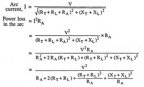
Power loss will be maximum when denominator will be minimum
i.e., Power loss in the furnace will be maximum when the arc resistance RA will be numerically equal to the impedance of the whole electrical circuit referred to the secondary excluding arc resistance RA.
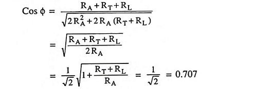
Power factor at maximum power loss,
Substituting (RT + RL)2 + (XT + XL)2 = R2A, we get
if we neglect RT + RL in comparison with RA. However, it is not economical to operate an arc furnace with primary side power factor under 0.8.
