Loss of Excitation Protection in Generator:
Loss of excitation protection in generator can endanger the generator or the connected system or both.
It is caused by accidental tripping of field breaker, short circuit in the field circuits, poor brush contact or operating errors. In absence of field current alternator runs as an induction generator and thus heavy currents are inducted in the rotor teeth and wedges. Most modern generators can only withstand these currents up to a period of 2 to 3 minutes. When a generator loses excitation, it draws reactive power from the system amounting as much as 2 to 4 times the generator’s rated load. Before it lost excitation, the generator may have been delivering reactive power to the system. Thus, this large reactive load suddenly thrown on the system, together with the loss of generator’s reactive power output may cause wide spread voltage reduction, which in turn, may cause extensive instability.
If the system is capable enough to tolerate the difference of reactive power then no automatic protection is required for the purpose as an operator has got 2 to 3 minutes to take care of it. But if there is chance of instability of the system, automatic protection is required.
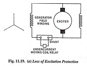
Undercurrent moving coil relay connected across a shunt in series with the field winding for loss of excitation protection in generator is illustrated in Fig. 11.19 (a).
In case of large generators which operate over a wide range of field excitation such a relay may be an embarrassment.
Furthermore, field failure due to failure of exciter may not be detected by it as it may be held in by ac induced from the stator. An undercurrent relay fast enough to drop out on ac cannot be employed as it would be affected by ac induced during synchronizing and during external faults.
The most selective type of loss of excitation relay is a directional distance type relay operated from alternating current and voltage at the main generator terminals.
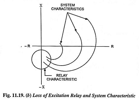
Several loss of excitation protection in generator characteristics and the relay operating characteristic on an R-X diagram are illustrated in Fig. 11.19 (b). As soon on the excitation is lost, the equivalent generator impedance traces a curve from the first quadrant of R-X diagram into a region of the fourth quadrant. By enclosing this region within the relay operating characteristic, the relay will operate when the generator first starts to slip poles and will trip the field breaker as well as disconnect the generator from the system before either the generator or the system can be harmed. The generator may then be returned to service immediately when the cause of excitation failure is corrected.

