AC Excitation System – Block diagram and Working Principle:
This AC Excitation system consists of an alternator and thyristor rectifier bridge directly connected to the main alternator shaft. The main exciter may either be self excited or separately excited. A rotating thyristor excitation system employs self excited main exciter whereas the brushless excitation system employs a separately excited main exciter.
1. Rotating Thyristor Excitation System:
Block diagram of a rotating thyristor excitation system is depicted in Fig. 19.2, the rotating portion being shown enclosed by dashed line rectangle. This AC Excitation system comprises of an ac exciter having a stationary field and a rotating armature. The exciter output, rectified by a full-wave thyristor bridge rectifier circuit, is supplied to the main alternator field winding. The alternator field winding is also supplied from the exciter output through another rectifier circuit. Exciter voltage can be built up using its residual flux. For convenience and to shorten the build up time, stationary battery supply is also incorporated.
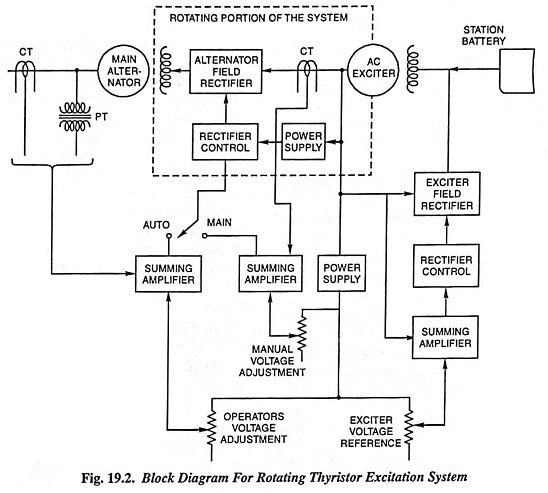
The power supply and rectifier control, incorporated as a part of rotating portion, generates the required phase controlled triggering signals in response to a dc control level fed by the voltage regulator.
An automatic voltage regulator (AVR) is also incorporated in the AC Excitation system. The alternator voltage signal (from the PT) is averaged and compared directly with the operators voltage adjustment (voltage reference) in the auto mode of operation. In the manual mode of operation the excitation current of the alternator is compared with a separate manual voltage adjustment (reference) and supplied to the rotating thyristor bridge through separate regulating elements.
For maintaining the terminal voltage of the exciter at the desired level, the exciter voltage is averaged, compared with the exciter voltage reference and applied to the rectifier control and rectifier in a suitable manner.
The AC Excitation system also incorporates additional features like overvoltage protection, overcurrent protection in the exciter field control, lead-lag compensation for stabilization of voltage control, watt and VAR signals for regulating the voltage and field discharge resistor, which are not shown in the block diagram.
2. Brushless Excitation System:
With the increase in rating of alternators, the problem of brush maintenance gets more and more complicated, so the brushless excitation systems are becoming more and more popular. The advent of silicon diodes and thyristors made it possible to have compact rectified system converting ac to dc at higher power levels.
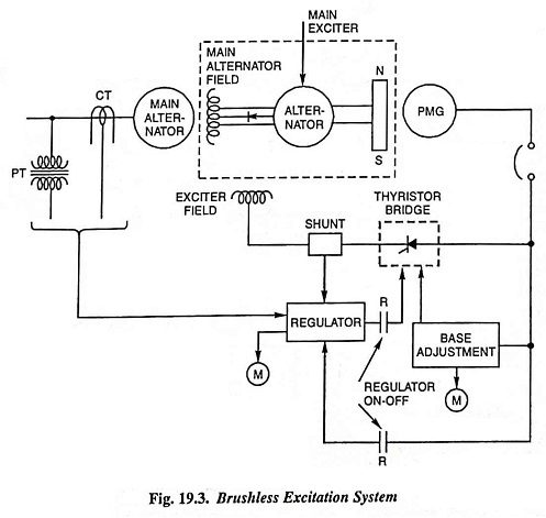
This system is depicted in Fig. 19.3, the rotating portion being shown enclosed by a dashed line rectangle. The AC Excitation system comprises of an alternator rectifier main exciter and a permanent magnet generator (PMG) pilot exciter. Both of the main and pilot exciter are driven directly from the main shaft. The main exciter has a stationary field and a rotating armature directly connected, through silicon rectifiers, to the field of the main alternator. The pilot exciter is a shaft driven permanent magnet generator having rotating permanent magnets attached to the shaft and a 3-phase stationary armature, which feeds the main exciter’s field through 3-phase full-wave phase controlled thyristor bridges. This system eliminates the use of commutator, collectors and brushes and has a short time constant and a response time of less than 0.1 second. The short time constant has the advantage in improved small signal dynamic performance and facilitates the application of supplementary power system stabilizing signals.
3. Static Excitation System:
Figure 19.4 depicts the static excitation system using SCRs.
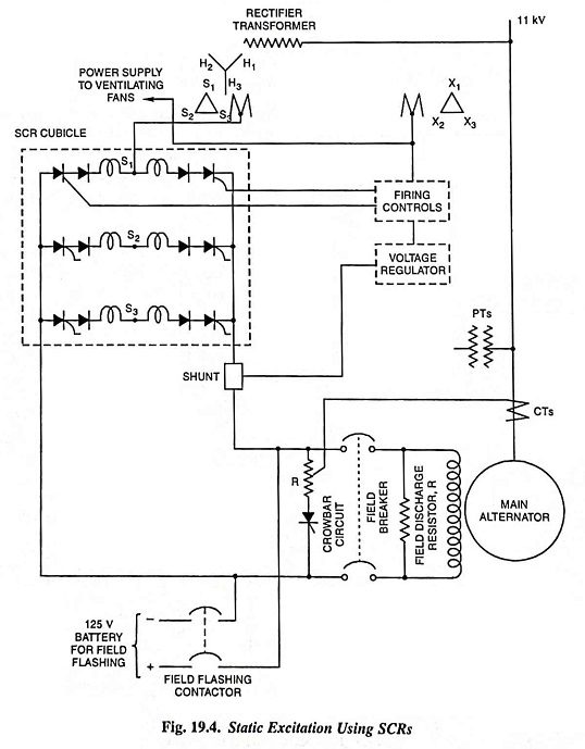
In static AC Excitation system, the excitation supply is taken from the alternator itself through a 3-phase star/delta connected, oil immersed, forced air cooled, indoor type step-down transformer and a rectifier system employing mercury-arc rectifiers or silicon controlled rectifiers. The star-connected primary is connected to the alternator bus, the delta-connected secondary supplies power to the rectifier system and the delta-connected tertiary feeds power to grid control circuits and other auxiliary equipment. The rectifiers are connected in parallel to give sufficient current carrying capacity. Each leg of rectifier is protected with series fuse, surge protection and fault indicating light. The rectifiers are forced air cooled. This system has a very small response time (about 20 milliseconds) and provides excellent dynamic performance.
SCRs are ideally suited for a static excitation system because they have high speed of response, high power gain and can be easily paralleled.
Advantages:
The advantages of the static excitation system are elimination of exciter windage loss and commutator wearing and winding maintenance resulting in reduced operating costs and electronic speed response. The fact that in static excitation the voltage is proportional to the speed, affords a major advantage in load rejection.