AC Analysis of BJT Circuits Articles:
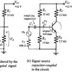
Coupling and Bypassing Capacitors: Coupling Capacitors – To use a transistor circuit to amplify or otherwise process an ac signal, the signal source must be connected to the circuit input. If the source is directly connected to the input, as illustrated … (Read More)
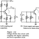
AC Load Line of BJT: AC Equivalent Circuits – Capacitors behave as short-circuits to ac signals, so in the ac equivalent circuit for a transistor circuit all capacitors must be replaced with short-circuits. Power supplies also behave as ac short-circuits, because … (Read More)
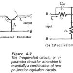
Transistor Models and Parameters: T-Equivalent Circuit – Because a transistor consists of two pn-junctions with a common centre block, it should be possible to use two pn-junction ac equivalent circuits as the Transistor Models and Parameters. Figure 6-9 shows the ac … (Read More)
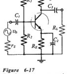
Common Emitter Amplifier Circuit: Consider the Common Emitter Amplifier Circuit circuit shown in Fig. 6-17. When the capacitors are regarded as ac short-circuits, it is seen that the circuit input terminals are the transistor base and emitter, and the output terminals … (Read More)
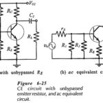
CE Circuit with Unbypassed Emitter Resistor: h-parameter Equivalent Circuit – When an CE Circuit with Unbypassed Emitter Resistor (RE) as shown in Fig. 6-25(a), it is also present in the ac equivalent circuit, . RE must also be shown in the … (Read More)
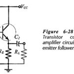
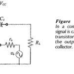
Common Collector Circuit Analysis: In the Common Collector Circuit Analysis (CC) shown in Fig. 6-28 the external load (RL) is capacitor-coupled to the transistor emitter terminal. The circuit uses voltage divider bias to derive the transistor base voltage (VB) from the supply. … (Read More)
Common Base Circuit Diagram: The Common Base Circuit Diagram (CB) shown in Fig. 6-34 is very similar to a CE circuit, except that the input signal is applied to the transistor emitter terminal (via C2), instead of the base. Also, there … (Read More)
Difference Between Common Base Common Emitter and Common Collector: Table 6-2 compares Zi, Zo, and Av, for difference Between Common Base Common Emitter and Common Collector circuits. As already discussed, the CE circuit has high voltage gain, medium input impedance, high output … (Read More)