AC Winding:
Ac winding are generally of a 3-phase kind because of the inherent advantages of a 3-phase machine. The armature coils must be connected to yield balanced (equal in magnitude and successive phase difference of 2π/3 rad) 3-phase emfs. To begin with the slots around the armature periphery must be divided into phase-bands.
Phase Grouping:
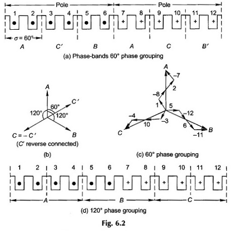
Initially a simple case will be assumed where SPP is an integral number; such AC Winding is referred to as integral-slot winding. For illustrative purposes, let m = 2 which means 12 slots per pole pair for a 3-phase armature. Slot angle is 360°/12 = 30°. Further let the coil-pitch be full six slots. Figure 6.2(a) shows the 12 slots numbered from left to right; six slots are under the influence of one pole with a particular direction of emfs in coil-sides and the remaining six slots are under opposite pole with opposite direction of emfs as indicated.
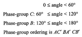
In Fig. 6.2(a) the 12 armature slots are divided into six phase-bands of two (= m) slots each having an angular spread of σ = 60°; in fact each pole is divided into three bands (as many as the number of phases). If coil-sides in slots (1, 2) belong to phase band A, those in slots (5, 6) which are 120 (or four slots) away belong to phase band B and those in slots (3, 4) are 60 (or two slots) away from A Which when reverse-connected would belong to phase C. (See phasor diagram of Fig. 6.2(b).) Therefore coil-sides in slots (3,4) are said to belong to phase band C’. As a result of this arrangement the phase-band sequence is AC’ BA’ CB’ which will repeat for each pair of poles. This arrangement of phase-band is called 60° phase grouping. The four coil-sides of each pair of coils of a phase can be connected additively in any order. For example, the order of the coil-side connection for phase A could be (1-8-2-7) as used in a single-layer winding with concentrated coils or it could be (1-7-2-8) in a two-layer lap winding. The phasor diagrams of all the three phases for the former kind of connection is given in Fig. 6.2(c).
The 60° phase grouping discussed above can be used for single-layer or double-layer AC winding. It is also possible to use a 120° phase grouping where the slots under a pole pair are divided into three phase-bands as in Fig. 6.2(d). For the example in hand there are four slots per phase-band. It is obvious that slots for return coil-side for this phase-grouping will not be available in single-layer winding. It can only be used for a double-layer winding. A phase-grouping of 120° is rarely adopted and will not be discussed any further.
Types of Winding:
- Single Layer Winding Diagram
- Concentric Winding
- Double Layer Winding Diagram
- Integral Slot Winding
- Fractional Slot Winding
Single Layer Winding Diagram:
Single Layer Winding Diagram are not commonly used in practice except for machines of a few kW because of the disadvantages mentioned earlier. Single Layer Winding Diagram may be concentric, lap or wave type. Here only the concentric type winding will be illustrated while the lap type will be explained in two-layer winding. Wave winding because of certain problems in end connections is not used in AC Winding machines.
Concentric Winding:
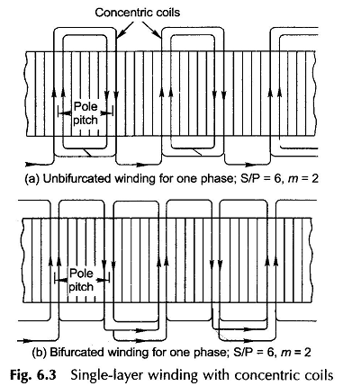
Concentric winding may be classified into two main categories, viz. unbifurcated (or half-coiled) and bifurcated (whole-coiled). In the former type the coils comprising a phase group in adjacent pole pitches are concentric as indicated in Fig. 6.3(a). The individual coils may have a span greater or less than a pole pitch but the average coil-span equals one pole-pitch. This kind of arrangement is provided to avoid crossing of two coils under one phase-group. In bifurcated AC winding, each coil group is split into two sets of concentric coils and the return coil-sides are shared with those of another group as shown in Fig. 6.3(b). It is clearly evident from the figure that this kind of arrangement is only possible when SPP is even.
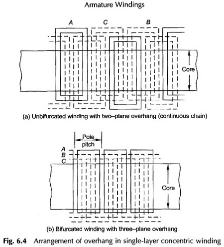
It is easily seen from Figs 6.3(a) and (b) that for accommodating the AC winding for all the three phases, the overhang must be arranged in two or three planes. Figure 6.4(a) which corresponds to unbifurcated winding (Fig. 6.3(a)), the overhang is arranged in a continuous chain with sequence (if seen from a fixed reference) where upward and downward arrows indicate the upper and lower planes. The three plane overhang arrangement of a bifurcated winding is depicted in Fig. 6.4(b).
Single-layer coils can be arranged in semi-closed slots (the coil is opened and pushed in slots from one side, the coil then being reformed and reconnected by buff-welding).
Chording and the use of fractional SPP is not possible in a single-layer winding. As will be seen in the next section, it is a serious drawback.
Double Layer Winding Diagram:
Double Layer Winding Diagram are the most widely used class of windings. Though both lap and wave types are possible, because of inherent problems of a wave winding, it is now an accepted practice to use the lap type for double-layer ac winding.
Double layer windings fall into two main classes depending upon the value of SPP—integral slot winding when SPP is an integer and fractional slot winding when SPP is a fractional number. To meet the requirement of symmetry among phases, the number of slots/phase (S/3) must be a whole number.
Integral Slot Winding:
Here SPP is an integer. The AC winding arrangement is further illustrated through an example. Let
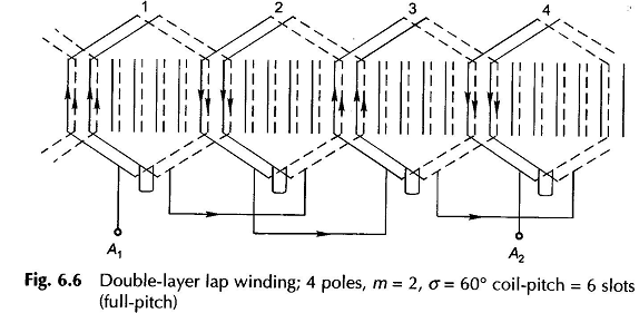
The AC winding diagram for one phase is shown in Fig. 6.6. The first set of phase-group coils (coil-group 1) lying under one pole-pair are connected in series (finish end of the first coil is connected to the start of the next coil lying to the right of the first). The second coil-group of the phase lies under SN poles and must therefore be connected in reverse to the first coil-group for additive emf. It may be noticed that alternate coil-groups are reverse connected. It is observed that the winding appears like a bifurcated one. It is also observed that coil-sides lying in any given slots pertain to the same phase. All the coil-groups of the phase could be connected in series or in series-parallel.
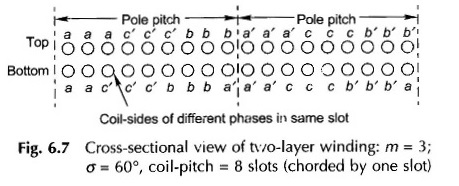
In practice, however, it is common to use chorded or short-pitched coils. As already mentioned, this type of arrangement offers certain inherent advantages such as reduction in copper needed for end connections. Further, certain harmonics present in the emf wave are greatly suppressed. However, coil chording leads to a reduction in the emf generated. This type of winding is best illustrated by means of a cross-sectional developed diagram. Here letters (a, b, c) refer to the coil-sides of the corresponding phase. For the example considered,
The cross-sectional view of AC winding for one pole-pair is drawn in Fig. 6.7. Certain observations can be made from this figure. The top and bottom coil-side phase-grouping is merely displaced by one slot (equal to chording). Further. in each phase-group of three slots, the coil-sides of two different phases are placed in one of the slots.
Fractional Slot Winding:
So far these types of windings have been studied in which SPP is an integer. Windings, wherein SPP is a fractional number, are known as fractional slot windings. Fractional slot winding is easily adopted with a double-layer arrangement.
While m = S/3P is a noninteger in a fractional slot winding, S, the number of slots, must be divisible by 3, i.e. slots per phase must be integral in order to obtain a symmetrical 3-phase winding. The pole pitch, S/P, is also fractional, so that the coil-span cannot be of full-pitch. For example if S/P = 10.5, then the coil-span can be either 11 or 10 slots. The coil-span chosen is of course less than the full-pitch because of the inherent advantages of chording elaborated earlier.
In the previous discussion it has been learnt that winding constituting a basic unit under a pole-pair (N and S) is repeated for any number of pole pairs when m is integral. In order to obtain the “basic unit” for fractional slot winding, S/3P is reduced to the irreducible fraction by cancelling out the highest common factor in S and P.
Coil-sides under P’ poles constitute the basic unit whose connections will be repeated P/P’ times in the complete winding. It will soon be evident that P cannot be a multiple of three in a 3-phase winding.
In a double-layer winding, the phase-grouping of coil-sides for the top layer is repeated in the bottom layer with corresponding coil-sides being located one coil-span away. Therefore, all that is needed is to establish the phase-grouping of top layer of coil-sides.
Fractional slot winding is easily understood by means of an example.
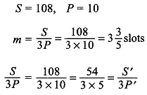
Let
Thus the basic unit in this winding has 5 poles (note that this need not be even) covering 54 slots.
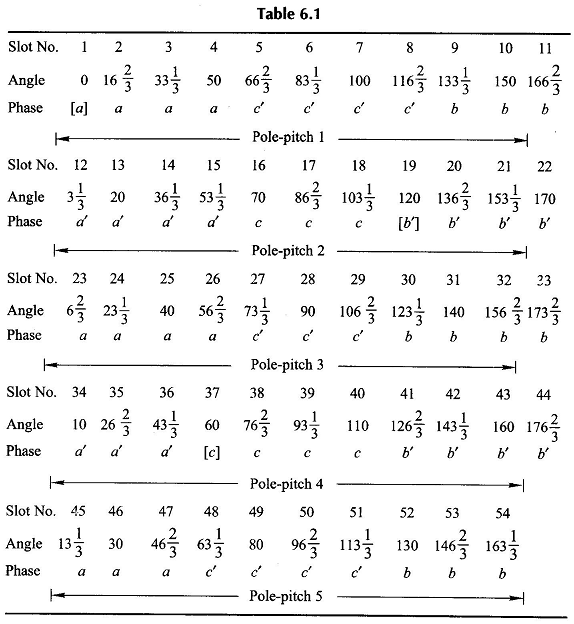
A coil-group table (Table 6.1) is now prepared on the following lines
- Calculate the slot angle,
- Beginning with 0°, calculate the angle for serially arranged slots in a table. Every time the angle exceeds 180°, subtract 180°, the angle of one pole- This takes care of the fact that the positive direction of emfs under adjacent poles are in opposite direction.
- Phase-group A is located corresponding to:
- The starting points of phases are located at 0°, 60° and 120°. While 0° is the start, the other two angles are located at S’/3 = 18 and 2S’/3 = 36 slots away.
These angles are 60°, 120° or their multiples for any P′ except when P′ is multiple of 3 (= number of phase). Thus if P’ (or P) is multiple of 3, balanced winding is not possible.
It is immediately seen from the last rows of Table 6.1 that there are three cycles of (4, 4, 3, 4, 3) slot distribution starting at slot no. 1(0°, phase A), slot no. (1 + S’/3)= 19 (120°, phase B) and slot no. (1 + 2S’/3) = 37 (60°, phase C). So this pattern results in a balanced winding.
Figure 6.8 shows the layout of the winding for the basic unit of five poles indicating the number of coils and their phase-groups. The dashed phase-groups are reverse connected. The start of all the three phases is made at the start of an undashed coil-group. This winding pattern would repeat for every 5-pole unit. It, therefore, represents the winding diagram for 10, 20, . . . pole armature.
Advantages of AC windings:
Though the fractional slot winding may appear to be somewhat complicated, it has certain technical advantages and can be easily manufactured. The number of armature slots chosen need not necessarily be an integral multiple of the number of poles. Consequently one may choose a particular number of slots for which the notching gear is available. This results in saving in machine tools. This flexibility can be effectively used where the number of poles (machine speed) varies over a wide range as in the case of synchronous machines.
Furthermore, the high-frequency harmonics caused by slotting are considerably reduced by the use of fractional slot winding. As the poles move past a slotted armature, the flux/pole fluctuates (does not move) as the slot-teeth pattern facing a pole repeats. This causes induction (static) of emf harmonics of high frequency. If S/P is integral, the disposition of armature slots relative to pole simultaneously repeats (in time phase) at every pole so that the harmonics in phase-groups of a given phase are in phase. Nonintegral S/P causes the harmonics in phase-group to become outof-phase thereby reducing their strength in the phase voltage.
