Analog Electronics Process Controllers:
An Analog Electronics Process Controllers must be capable of providing one or more of the three main methods of control, namely, Proportional, Integral and Derivative.
The circuits described in this section use high gain OPAMP’S with specially designed feedback circuits. They operate with their phase inverting input as a virtual earth point. If the amplifier saturates due to, say, a high value of input signal (i.e. deviation signal), the phase inverting input may no longer remain virtual earth point and circuit theory becomes invalid.
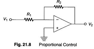
The simplest form is the proportional control shown in Fig. 21.8, which has an overall voltage gain of
Hence, V2 = — V1R2 / R1, so that the output voltage is proportional to the input voltage. The value of the proportional band of the controller is modified by changing the value of R1 and R2. The input voltage V1 in all the circuits in Fig. 21.8 is either deviation (error signal) or it is amplified version of the deviation. The negative signal associated with Eq. 21.1 implies that the output voltage has the opposite polarity of V1.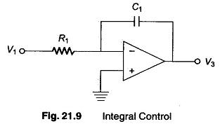
Pure integral action is as obtained from the circuit in Fig. 21.9. Integral circuit is often Used in conjunction with proportional control (two-term control or PI control) as a means of reducing the steady state deviation or offset.
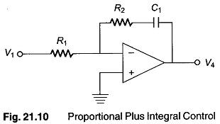
Figure. 21.10 is a realistic version of proportional plus integral controller. The magnitude of the proportional gain factor is given by R2/R1 and the integral action time is R1C1 (R in Ω and C in Farads).
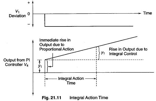
The integral action time of a proportional plus integral controller can best be explained in terms of the output waveform from the Analog Electronics Process Controllers for a step change or sudden change in the input (deviation) signal shown in Fig. 21.11.
Since the OPAMP in Fig. 21.10 is an inverting amplifier, a negative step change in input voltage is applied to produce a positive output voltage change. As soon as the step change is applied, the P action of the controller causes the output voltage to change suddenly by Y1 volts. The action of the integrator capacitor then causes the controller output voltage to begin to rise at a steady rate and it takes a time known as the integral action time for the output voltage to rise by a further Y1 volts.
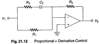
Derivative (D) control provides a stabilizing influence on the system and is desirable in a system in which the value of the controlled variable changes rapidly. A basic proportional plus derivative controller is shown in Fig. 21.12, the P action being provided R1 and R2 , while the derivative action is provided by capacitor C2 together with R3 .
When the system is in its steady state, the value of the deviation signal (V1) is constant and capacitor C2 is charged to a constant value equal to V1 (the non-inverting terminal being at virtual ground). Hence no current flows through C2, under this condition the magnitude of the voltage gain (V5/V1) is equal to R2/R1.
However, when the deviation (V1) changes rapidly, capacitor C2 charges rapidly and presents little impedance to the flow of current. The net effect is that R3 can be considered as being in parallel to R1, but since R3 value used in a practical circuit is typically one tenth that of R1, the combined resistance of the input circuit is very nearly equal to R3. The amplifier gain under this conditions is approximately equal to R2/R3 which is 10 times greater than the gain under steady state conditions. That is, the action of the derivative control while the deviation is changing rapidly is to reduce the proportional bandwidth of the controller. The net effect is to cause a more rapid change in the controller output, thereby resulting in a more rapid change in the controlled variable. When steady state conditions are finally reached, capacitor C2 is charged to the new steady value of V1, and the magnitude of the gain again becomes R2/R1. The derivative action time of the proportional plus derivative controller is R1C2.
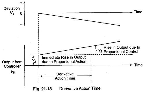
The derivative action time of a P plus D action controller can be explained in terms of the output waveform of the controller for a ramp change in input signal, in other words for a constant change in the deviation signal shown in Fig. 21.13. Since the op-amp is inverting, a negative ramp signal is applied in order to get a positive going output voltage. As soon as the amplifier change in the input signal is applied. The derivative action of capacitor C2 causes the output voltage to suddenly change by Y2 volts. The P action to the controller causes the output voltage to rise at a constant rate, and takes a time known as the derivative action time for the output voltage to rise by a further Y2 volts. In this case, the derivative action time is given by R1C2 of the controller.
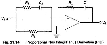
The block diagram of a 3-term controller providing P + I + D (PID) control is shown in Fig. 21.14.
Resistors R1 and R2 provide the basic P control, while capacitor C1 introduces integral control and capacitor C2 derivative control.
A pactical form of 3-term controller together with a clipping circuit or desaturation circuit which prevents the virtual earth concept being violated if the amplifier saturates is shown in Fig. 21.15.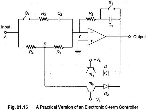
The clipping circuit, consists of transistors Tr1 and Tr2 together with diodes D1 and D2 The diodes do not function so long as the output voltage does not exceed about ± (VL + 1) volts, if VL = 7 V then clipping circuit does not come into operation for any output voltage within the range +8 to —8 V. If the output voltage tends to exceed +8 V, due to say, sudden change in V1, diodes D1 and transistor Tr1 begins to conduct, and connect point X to the output terminal. This results in the change being diverted through resistor R4 whose value is very low when compared with that of R1 (the value of R4 is typically 0.5% of R1), with the result that point Y remains virtual ground. Similar effects take place by Tr2 and D2 for a negative output voltage greater than about —8 V (assuming, i.e. —VL = —7V).
When switch S1 is closed and S2 is open, the circuit provides proportional action only, the magnitude of the voltage gain being R2/R1 , the proportional band of the controller can be changed by changing value of this ratio.
With Si and S2 open, the controller becomes a proportional plus integral controller with an integral action of T1 = R2CL
With S1 closed and S2 closed, the circuit provides proportional plus derivative action with a derivative action time of T2 = R1C2.
With S1 open and S2 closed, 3-term control is obtained, the integral action time T1 and derivative action time TD of this controller are
where T1 and T2 are given above. The magnitude of the overall voltage gain of the amplifier is given by
while the output forms an Analog Electronics signal, it can be converted into air pressure by a suitable interface device.

