Analysis of Unsymmetrical Faults:
In the Analysis of Unsymmetrical Faults, the following assumptions will be made :
- The generated e.m.f. system is of positive sequence only.
- No current flows in the network other than due to fault e. load currents are neglected.
- The impedance of the fault is zero.
- Phase R shall be taken as the reference phase.
In each case of Analysis of Unsymmetrical Faults, e.m.f.s’ per phase are denoted by ER,EY and EB and the terminal p.d. per phase by VR, VY and VB.
Single Line to Ground Fault:
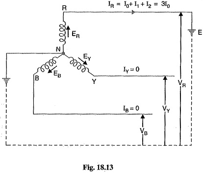
Consider a 3-phase system with an earthed neutral. Let a single line-to-ground fault occur on the red phase as shown in Fig. 18.13. It is clear from this figure that :
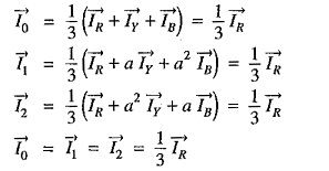
The sequence currents in the red phase in terms of line currents shall be :
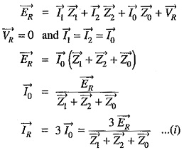
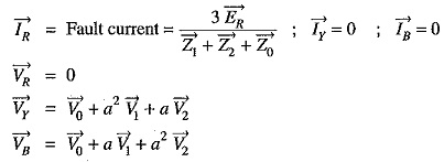
Fault current: First of all expression for fault current IR will be derived. Let Z1,Z2 and Z0 be the positive, negative and zero sequence impedances of the generator respectively. Consider the closed loop NREN. As the sequence currents produce voltage drops due only to their respective sequence impedances, therefore, we have,
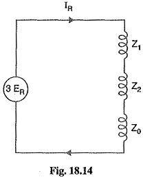
Examination of exp. (1) shows that the equivalent circuit from which fault current may be calculated is as given in Fig. 18.14. It is clear that fault current is obtained by connecting the phase sequence impedances in series across an imaginary generator of voltage 3 ER. This is a wonderful part of the method of symmetrical components and makes the analysis easy and interesting. In fact, this method permits to bring any Analysis of Unsymmetrical Faults into a simple circuit of interconnection of sequence impedances appropriate to the fault condition prevailing.
The assumption made in arriving at exp. (i) is that the fault impedance is zero. However, the fault impedance is Ze, then expression for fault current becomes :
It may be added here that if the neutral is not grounded, then zero sequence impedance will be infinite and the fault current is zero. This is expected because now no path exists for the flow of fault current.
Phase voltages at fault: Now let us calculate the phase voltages at fault (i.e. voltage between each line and fault). Since the generated e.m.f. system is of positive sequence only, the sequence components of e.m.f. in R-phase are :
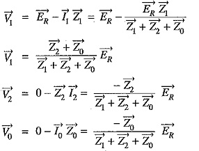
The sequence voltages at the fault for R-phase are :
It can be readily seen that V1+V2+V0=0. This is expected because R-phase is shorted to ground.
The phase voltages at fault are :
For line (R-phase)-to-ground fault :
Line to Line Fault:
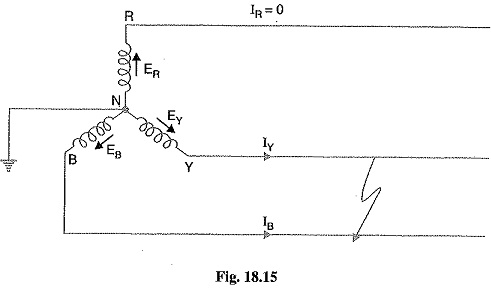
Consider a line-to-line fault between the blue (B) and yellow (Y) lines as shown in Fig. 18.15. The conditions created by this fault lead to![]()
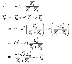
Again taking R-phase as the reference, we have,
Expressing in terms of sequence components of red line, we have,
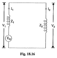
Fault current: Examination of exp. (i) and exp (ii) reveals that sequence impedances should be connected as shown in Fig. 18.16. It is clear from the figure that :
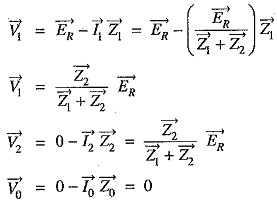
Phase voltages: Since the generated e.m.f. system is of positive phase sequence only, the sequence components of e.m.f. in R-phase are :![]()
The sequence voltages at the fault for R-phase are :
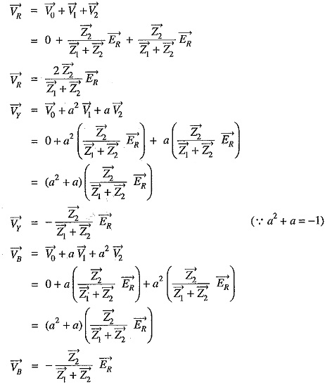
The phase voltages at fault are :
For line-to-line fault (Blue and Yellow lines) :
Double Line to Ground Fault:
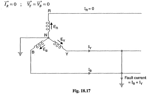
Consider the double line-to-ground fault involving Y-B lines and earth as shown in Fig. 18.17. The conditions created by this fault lead to :
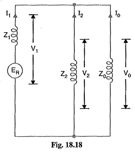
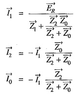
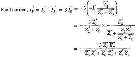
Fault current: Examination of exp. (i) and exp. (ii) reveals that sequence impedances should be connected as shown in Fig. 18.18. It is clear that :
Phase Voltages: The sequence voltages for phase R are :
