Application of Permanent Magnet Motor:
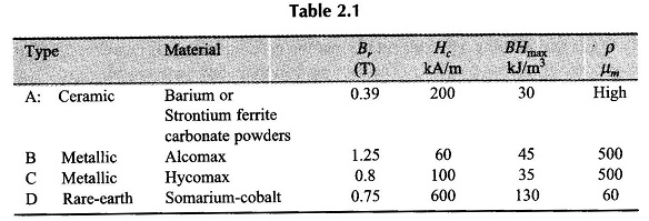
Application of Permanent Magnet Motor are given in Table 2.1. These properties are: residual flux density Br, coercive magnetizing force Hc maximum energy stored (BH)max and resistivity.
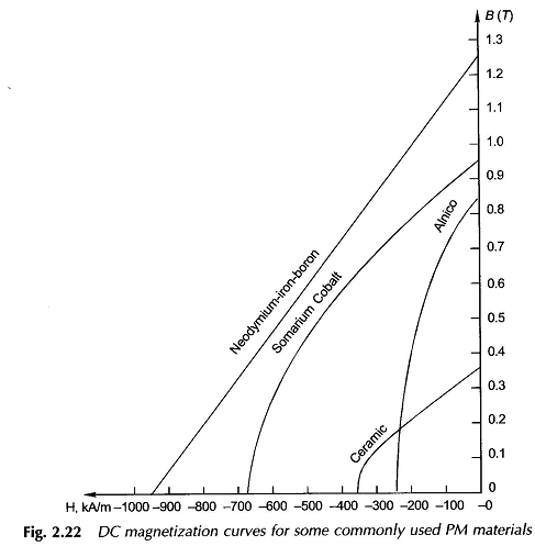
Type A material is cheap but heavy, and suitable for low-rated production-run motors. Types B and C materials are hard and can be given simple shapes only. Type D material can be easily moulded and machined and is used for most electric motors but is costly. Application of Permanent Magnet Motor with higher coercivities are much less prone to demagnetization. Figure 2.22 shows DC magnetization curves for a few commonly used materials.
The latest of the rare-earth magnetic materials is the neodymium-iron-boron material. It has larger Br,Hc and (BH)max than Somarium cobalt. It is cheaper and has good mechanical properties and this is expected to be used in a big way for PM applications.
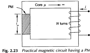
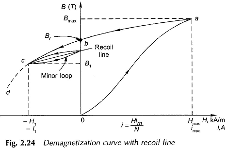
Consider the magnetic circuit of Fig. 2.23 consisting of a section of PM material in a core of highly permeable soft magnetic material with an N-turn exciting winding. Figure 2.24 shows that the PM is initially unmagnetized and current is applied to the exciting winding. As core is of infinite permeability, the X-axis represents both i and H.
As current i is raised to its maximum value (saturation), the BH trajectory rises from the origin to its maximum value at point ‘a’. Now if the current is reduced to zero, the BH characteristic starts forming a hysteresis loop meeting Y-axis at point b at which B= Br and H= 0.
As the current is further decreased to a negative value the BH curve continues to follow a hysteresis loop as shown in Fig. 2.24. For i = -i1, the operating point is c. It may be noted that the same operating point c would be arrived (see Ex. 2.7) if the material were to start at point b with zero excitation and air-gap length of lm (Ag/Am) (-μ0H1/B1) (Eq.(12.42)) were then inserted in the core.
If the current is further reduced, the trajectory would further trace the BH curve toward d as shown in Fig. 2.24. However, if the current is reduced to zero, the trajectory does not normally retrace the loop toward point b. Instead it starts to trace out a minor hysteresis loop, as shown in Fig. 2.24. As the current varies from 0 to i1. The minor hysteresis loop may usually be replaced with little error by a straight line called the recoil line. This line has a slope called the recoil permeability μrec, which is approximately the same as that of the original BH curve at H= 0, i.e., at B = Br. In fact the recoil line is essentially tangent to the BH curve for a large portion of the useful operating region for many materials such as Somarium Cobalt, Ceramic 7 etc. having large values of coercivity.
As long as the negative value of applied magnetic field intensity does not exceed H1, the magnet may be regarded as reasonably permanent. If, however, a negative field intensity greater than H1 is applied, the flux density will be reduced to a value lower than B1 and a new and lower minor loop will be created with a new recoil line and recoil permeability.
The demagnetization effects of negative excitation which have been discussed above are equivalent to those of an air-gap in the magnetic circuit.
Thus, we see that these materials produce enough magnetic flux even in magnetic circuits with air-gaps. With proper design they can be operated stable even when subjected to a wide range of destabilizing forces and mmf’s. Application of Permanent Magnet Motor are increasingly finding greater applications in many small devices such as loud speakers, ac and dc motors, microphones, analog electric meters, driving, windshield wipers, radio antennas, airconditioners, etc.


