Approximate Equivalent Circuit of Transformer:
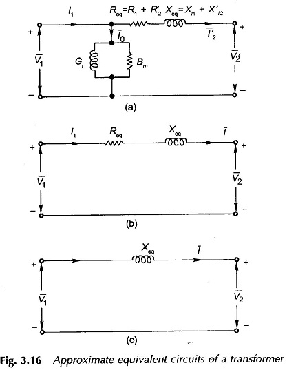
Approximate Equivalent Circuit of Transformer – In constant frequency (50 Hz) power transformers, approximate forms of the exact T-circuit equivalent of the transformer are commonly used. With reference to Fig. 3.14(c), it is immediately observed that since winding resistances and leakage reactances are very small, V1 ≈ E1 even under conditions of load. Therefore, the exciting current drawn by the magnetizing branch (Gi || Bm) would not be affected significantly by shifting it to the input terminals, i.e. it is now excited by V1 instead of E1 as shown in Fig. 3.16(a). It may also be observed that with this approximation, the current through R1, Xl1 is now I′2 rather than I1=I0+I′2 . Since I0 is very small (less than 5% of full-load current), this approximation changes the voltage drop insignificantly. Thus it is basically a good approximation.
The winding resistances and reactances being in series can now be combined into equivalent resistance and reactance of the transformer as seen from the appropriate side (in this case side 1). Remembering that all quantities in the equivalent circuit are referred either to the primary or secondary dash in the referred quantities and suffixes l, 1 and 2 in equivalent resistance, reactance and impedance can be dropped as in Fig. 3.16(b).
In computing voltages from the Approximate Equivalent Circuit of Transformer, the parallel magnetizing branch has no role to play and can, therefore, be ignored as in Fig. 3.16(b).
The Approximate Equivalent Circuit of Transformer offers excellent computational ease without any significant loss in the accuracy of results. Further, the equivalent resistance and reactance as used in the approximate equivalent circuit offer an added advantage in that these can be readily measured experimentally, while separation of Xl1 and Xl2 experimentally is an intricate task and is rarely attempted.
The Approximate Equivalent Circuit of Transformer of Fig. 3.16(b) in which the transformer is represented as a series impedance is found to be quite accurate for power system modelling. In fact in some system studies, a transformer may be represented as a mere series reactance as in Fig. 3.16(c). This is a good approximation for large transformers which always have a negligible equivalent resistance compared to the equivalent reactance.
The suffix `eq’ need not be carried all the time so that R and X from now onwards will be understood to be equivalent resistance and reactance of the transformer referred to one side of the transformer.

