Audio Power Amplifiers Articles:
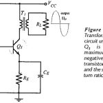
Transformer Coupled Class A Amplifier: Class A Circuit – Instead of capacitor coupling, a Transformer Coupled Class A Amplifier may be used to ac couple amplifier stages while providing dc isolation between stages. The resistance of the transformer windings is normally … (Read More)
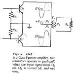
Transformer Coupled Class B Amplifier: Class B Amplifier – The inefficiency of Class-A amplifiers is largely due to the transistor bias conditions. In a Class-B amplifier, the transistors are biased to cutoff, so that there is no transistor power dissipation when … (Read More)
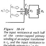
Transformer Coupled Amplifier: Transformer Coupled Amplifier commences with the load resistance and output power, specification. A signal voltage amplitude may also be stated, as well as the upper and lower cutoff frequencies for the amplifier. If a supply, voltage is given, … (Read More)
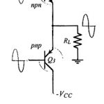
Complementary Emitter Follower Circuit: Two BJTs connected to function as Complementary Emitter Follower Circuit are shown in Fig. 18-17. Although one is npn and the other is prim the devices are selected to have similar parameters, so they are complementary transistors. … (Read More)
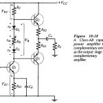
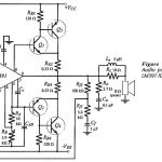
Capacitor Coupled Class AB Output Stage: The basic circuit of a Class-AB amplifier using a complementary emitter follower output stage and a Capacitor Coupled Class AB Output Stage load is shown in Fig. 18-18. The circuit is termed a complementary symmetry … (Read More)
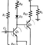
Direct Coupled Class AB Output Stage: The output capacitor in a capacitor-coupled power amplifier is a large expensive component that should be eliminated if possible. Figure 18-23 shows a Class-AB amplifier circuit with a Direct Coupled Class AB Output Stage. In this … (Read More)
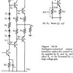
Darlington Connected Output Transistors: High-power transistors usually have low current gains, so relatively large base currents must flow into Q2 and Q3 to supply a high load current. This means that the quiescent current through Q1 must be large, and consequently … (Read More)
Quasi Complementary Output Stage: The Quasi Complementary Output Stage was originally developed because complementary high-power transistors were not readily available. Despite the fact that such transistors are now available, the Quasi Complementary Output Stage circuit is still widely used. Consider the arrangement … (Read More)
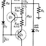
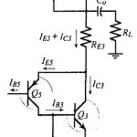
Output Current Limiting: Because the output transistors can be destroyed by excessive current flow, output current limiting circuits are often included in a power amplifier. Figure 18-27 shows the typical arrangement for a current limiting circuit. Emitter resistors RE2 and RE3 are … (Read More)
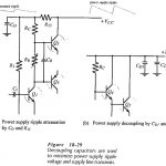
Power Supply Decoupling: High-power amplifiers require high supply current levels, so unregulated power supplies are often employed to avoid the power wasted in a series regulator. The high ripple voltage that occurs with unregulated supplies can be … (Read More)
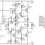
BJT Power Amplifier with Differential Input Stages: Amplifier Circuit – The direct-coupled amplifier in Fig. 18-33 has a BJT Power Amplifier with Differential Input Stages constituted by transistors Q1 and Q2. It also has an intermediate stage (Q3) with a constant … (Read More)
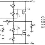 Complementary MOSFET Common Source Power Amplifier: Advantages of MOSFETs: Complementary MOSFET Common Source Power Amplifier have several advantages over power BJTs for large signal amplifier applications. One of the most important differences is that MOSFET transfer characteristics (ID/VGS) are more linear than … (Read More)
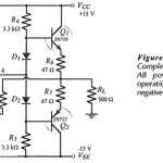
BJT Power Amplifier with Op Amp Driver: BJT Power Amplifier with Op Amp Driver Circuit Operation – The Class-AB power shown in Fig. 18-39 uses an operational amplifier (A1) for the input stage. Resistors R4 and R5 together with the two … (Read More)
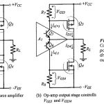
Common Source Power Amplifier Using an Op Amp Driver Stage: Basic Circuit Operation – The Class-AB MOSFET Power Amplifier with OP Amp Driver Stage circuit in Fig. 18-45(a) consists of an operational amplifier (A1), two MOSFETs (Q3 and Q4), and several … (Read More)
Audio Power Amplifier using IC Amplifier Driver: The LM391 integrated circuit Audio Power Amplifier using IC Amplifier Driver contains amplification and driver stages for controlling an externally-connected Class-AB output stage delivering 10 W to 100 W. The voltage gain and bandwidth … (Read More)
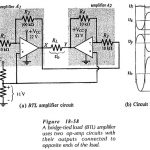
Bridge Tied Load Amplifier: All of the power amplifiers already discussed have been single-ended (SE): meaning that they provide power to a load that has one terminal grounded and the other terminal connected to the amplifier output. These amplifiers either use … (Read More)