AC Wheatstone Bridge
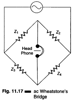
AC Wheatstone Bridge: Impedances at AF or RF are commonly determined by means of an ac Wheatstone bridge. The diagram of an ac bridge is given in Fig. 11.17. This bridge is similar to a…
Microprocessor Controlled Bridge: Microprocessor Controlled Bridge - Digital computers have been used in conjunction with test systems, bridges, and process controllers for several years. In these applications, computers were used to give instructions and perform…
Delayed Sweep Oscilloscope: Many oscilloscopes of laboratory quality include a delayed sweep feature. Delayed Sweep Oscilloscope feature increases the versatility of the instrument by making it possible to magnify a selected portion of an undelayed…
Various CRT Connections and Controls in CRO Panel: Figure 7.16 shows various controls and Typical CRT Connections. The following controls are available on CRO panel. Intensity: It controls the magnitude of emission of the electron,…
Fully Automatic Digital Instrument: Fully Automatic Digital Instrument - A multimeter with automatic polarity indication, automatic zero correction and automatic ranging (of course coupled with automatic decimal point indication) only needs a signal applied to…
Working Principle of Digital pH Meter | Block Diagram: Working Principle of Digital pH Meter - The Digital Measurement of hydrogen ion activity (pH) in a solution can be accomplished with the help of a…
Digital Tachometer Working Principle: Digital Tachometer Working Principle technique employed in measuring the speed of a rotating shaft is similar to the technique used in a conventional frequency counter, except that the selection of the…
Series and Shunt Compensation of Transmission Lines: The performance of long EHV AC transmission systems can be improved by reactive compensation of series or shunt (parallel) type. Series capacitors and shunt reactors are used to…
Load Commutated Chopper Circuit: In this method of Load Commutated Chopper Circuit, the load current flowing through the thyristor is made to become zero while the motor current is conducted by the free-wheeling diode. Figure…
Current Commutated Chopper Circuit: Figure 11.34 shows a Current Commutated Chopper Circuit. The main thyristor Th1 of the chopper is commutated by a current pulse generated in the commutation circuitry. The sequence of operation is…