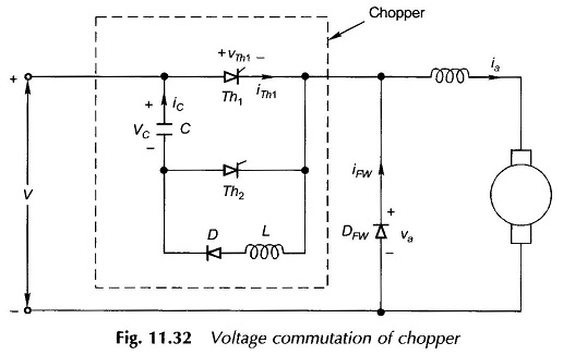
No Load Test of Induction Motor
No Load Test of Induction Motor: In this No Load Test of Induction Motor, the motor is run on no-load at rated voltage and frequency. The applied voltage and current and power input to motor…
Synchronous Sequential Circuits or Clocked Sequential Circuits: In Synchronous Sequential Circuits or clocked sequential circuits, clocked flip-flops are used as memory elements, which change their individual states in synchronism with the periodic clock signal. Therefore,…
Performance of CMOS Gates: The Performance of CMOS Gates which based on following different categories namely, Operating Speed : Slower than TTL series. Approximately 25 to 100 ns depending on the subfamily of CMOS Inverter…
CMOS NOR Gate Circuit: Fig. 3.4 shows 2-input CMOS NOR Gate Circuit. Here, P-channel MOSFETs Q1 and Q2 are connected in series and N-channel MOSFETs Q3 and Q4 are connected in parallel. Like NAND circuit, this circuit…
CMOS NAND Gate Circuit Diagram: Fig. 3.3 shows CMOS NAND Gate Circuit Diagram 2-input NAND gate. It consists of two P-channel MOSFETs, Q1 and Q2, connected in parallel and two N-channel MOSFETs, Q3 and Q4…
Parallel Adder and Subtractor: Parallel Adder and Subtractor which consists of three categories, namely, n Bit Parallel Adder,Binary Parallel Adder and n Bit Parallel Subtractor. n Bit Parallel Adder: We have seen, a single…
Half Subtractor and Full Subtractor Circuit: Subtractor are divided into two categories namely, half subtractor and full subtractor circuit. Half Subtractor Circuit: The Half Subtractor Circuit consists of four possible elementary operations, namely, In all…
Half Adder and Full Adder Circuit: Adders are divided into two categories namely, half adder and full adder circuit. Half Adder Circuit: The Half Adder Circuit operation needs two binary inputs : augend and addend…
Control Signals of 8085: The 8085 Microprocessor provides RD and WR signals to initiate read or write cycle. Because these Control Signals of 8085 are used both for reading/writing memory and for reading/writing an input…
Power on Reset Circuit in 8051: On reset, the PC sets to 0000H which causes the 8085 to execute the first instruction from address 0000H. For proper reset operation reset signal must be held low…