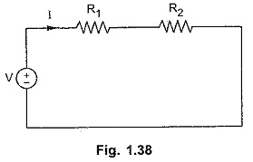
Series Circuit
Series Circuit: Series Circuit - The impedance diagram is a useful tool for analyzing series ac circuits. Basically we can divide the series circuits as RL, RC and RLC circuits. In the analysis of series…
Phasor Diagram Sine Wave: A phasor diagram can be used to represent a sine wave in terms of its magnitude and angular position. Examples of Phasor Diagram Sine Wave are shown in Fig. 5.5. In…
Impedance Diagram: Impedance Diagram is a complex quantity having real and imaginary parts; where the real part is the resistance and the imaginary part is the reactance of the circuit. Consider the RL series circuit…
Phase Relation in Pure Inductive Circuit: Phase Relation in Pure Inductive Circuit - As discussed already, the voltage current relation in the case of an inductor is given by Consider the function i(t) = Im sin…
Phase Relation in Pure Resistor: Phase Relation in Pure Resistor - When a sinusoidal voltage of certain magnitude is applied to a resistor, a certain amount of sine wave current passes through it. We know…
Measuring the Sine Wave: As the magnitude of the waveform is not constant, the Measuring the Sine Wave can be in different ways. These are instantaneous, peak, peak to peak, root mean square (rms) and…
Sine Wave Equation: A Sine Wave Equation is graphically represented as shown in Fig. 4.10(a). The amplitude of a sine wave is represented on vertical axis. The angular measurement (in degrees or radians) is represented…
Phase of Sine Wave: Phase of Sine Wave - A sine wave can be measured along the X-axis on a time base which is frequency-dependent. A sine wave can also be expressed in terms of…
The Sine Wave: Many a time, alternating voltages and currents are represented by a sinusoidal wave, or simply a sinusoid. It is a very common type of alternating, current (ac) and alternating voltage. The sinusoidal…
Attenuator Network: An attenuator network must fulfil following conditions. It must give correct input impedance, It must give correct output impedance and It must provide specified attenuation. In general, attenuation is expressed in decibel as…