Sinusoidal Response of RLC Circuit
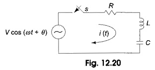
Sinusoidal Response of RLC Circuit: Consider a Sinusoidal Response of RLC Circuit consisting of resistance, inductance and capacitance in series as shown in Fig. 12.20. Switch S is closed at t = 0. At t=…
Comments Off on Sinusoidal Response of RLC Circuit
February 13, 2020