Ideal Transformer on Load
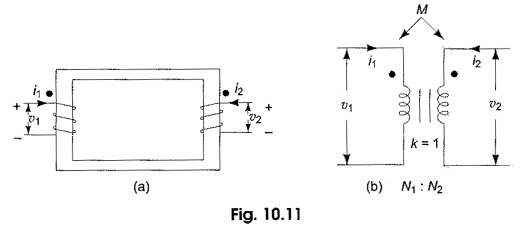
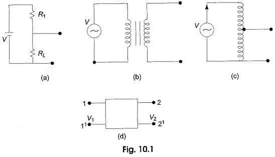
Ideal Transformer on Load: Transfer of energy from one circuit to another circuit through mutual induction is widely utilized in power systems. This purpose is served by Ideal Transformer on Load. Most often they transform…
Comments Off on Ideal Transformer on Load
December 28, 2019