Power in Three Phase Circuits
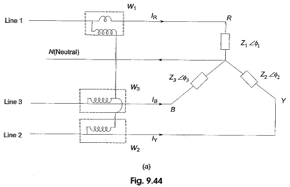
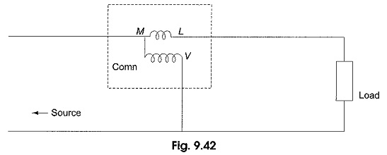
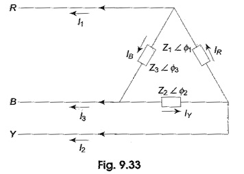
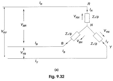
Power in Three Phase Circuits: Measurement of power by a wattmeter in a single phase circuit can be extended to measure Power in Three Phase Circuits. From earlier Section, it is clear that we require…
Comments Off on Power in Three Phase Circuits
December 26, 2019