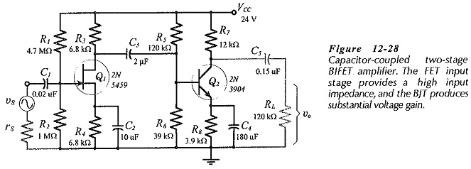
BIFET Amplifier
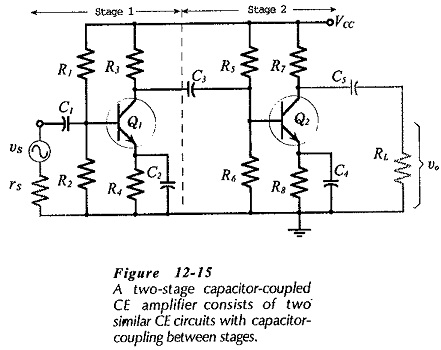
BIFET Amplifier: BJT-FET Considerations : Two-stage BJT circuits usually have relatively low input impedances. To increase Zi, a field effect transistor may be used as the first stage. Circuits which are composed of BJTs and…
DC Feedback Pair with Two Amplification Stages: The DC Feedback Pair with Two Amplification Stages circuit shown in Fig. 12-25(a). The base of transistor Q2 is directly connected to the collector of Q1, and the…
Two Stage Direct Coupled Common Emitter Amplifier: Figure 12-23 shows Two Stage Direct Coupled Common Emitter Amplifier. This time the second stage is a common collector circuit, or emitter follower. Stage 2 gives the circuit…
Direct Coupled Circuits: For economy, the number of components used in any circuit should be kept to a minimum. The use of direct coupling between stages is one way of eliminating components. Figure 12-20 shows…
Single Stage Common Source Amplifier: Bias circuit design for the Single Stage Common Source Amplifier in shown in Fig. 12-10. As with the common-emitter BJT circuit, design commences with specification of the supply voltage, amplification,…
Capacitor Coupled Two Stage CE Amplifier: A Capacitor Coupled Two Stage CE Amplifier circuit is shown in Fig. 12- 15 . Stage-1 is capacitor-coupled (via C3) to the input of Stage-2. The signal is applied…
Single Stage Common Emitter Amplifier Circuit: Specification - Bias circuit design for the Single Stage Common Emitter Amplifier Circuit in shown in Fig. 12-1 and ac analysis of the circuit is already explained. Design of…
Frequency Response of FET Amplifier: Low-Frequency Response - The low Frequency Response of FET Amplifier circuits is determined by exactly the same considerations as for BJT circuits. The lower cutoff frequency is normally set by…
FET and BJT Difference: FET and BJT Difference (CS, CD, and CG Circuit Comparison) - Table 11-1 compares Zi, Zo and Av for CS, CD, and CG circuits. As already discussed, the CS circuit has voltage gain,…
Common Gate Circuit: The FET Common Gate Circuit (CG) shown in Fig. 11-19 uses voltage divider bias. The ac output is taken from the drain terminal, and an external load (RL) is capacitor-coupled to the…