8259 Block Diagram
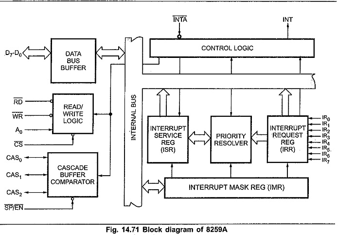
8259 Block Diagram: Fig. 14.71 shows the internal 8259 Block Diagram. It includes eight blocks : data bus buffer, read/write logic, control logic, three registers (IRR, ISR and IMR), priority resolver, and cascade buffer. Data…
Features of 8259 Programmable Interrupt Controller: The Features of 8259 Programmable Interrupt Controller are 1. It can manage eight priority interrupts. This is equivalent to providing eight interrupt pins on the processor in place of INTR…
Interfacing of 8257 with 8085: Fig. 14.68 shows the interfacing of 8257 with 8085 in I/O mapped I/O technique. In slave mode, RD and WR signals are activated by CPU when IO/M signal is high,…
Operating Modes of 8257: The Operating Modes of 8257 can be programmed to operate in following modes : Rotating Priority Mode : In rotating priority mode, the priority of the channels has a circular sequence.…
8257 Pin Diagram: Fig. 14.61 shows 8257 Pin Diagram. Data Bus (D0-D7) : These are bi-directional tri-state signals connected to the system data bus. When CPU is having control of system bus it can access…
Features of Microprocessor 8257 DMA Controller: The Features of Microprocessor 8257 DMA Controller are follows, 1. It is a programmable; 4-channel, direct memory access controller. Each channel can be programmed individually. Therefore, we can interface…
8257 DMA Controller: In microprocessor based systems data transfer can be controlled by either software or hardware. Upto this point we have used program instructions to transfer data from I/O device to memory or from…
Interfacing 8251 with 8085: Fig. 14.44 shows the Interfacing 8251 with 8085 in I/O mapped I/O technique. Here, RD and WR signals are activated by CPU when IO/M signal is high, indicating I/O bus cycle.…
8251 Usart: We know that, 8251A is Universal Synchronous, Asynchronous, Receiver, and Transmitter. Therefore 8251 Usart can take place with four different ways. Asynchronous transmission Asynchronous reception Synchronous transmission Synchronous reception These communication modes can…
8251 Block Diagram in Microprocessor: Fig. 14.37 shows the 8251 Block Diagram in Microprocessor. It includes : Data bus buffer, Read/Write control logic, modem control, Transmit buffer, Transmit Control, Receiver Buffer and Receiver control. Data…