Transistor Chopper Circuit
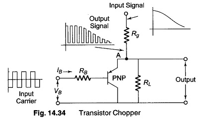
Transistor Chopper Circuit: Transistor Chopper Circuit - A single transistor used as a dynamic switch to convert low level dc signal to an ac waveform is shown in Fig. 14.34. If the voltage applied to…
Diode Bridge Type Modulator with Transformer Coupling: Diode Bridge Type Modulator - Figure 14.33 shows a silicon diode ring modulator with an associated ac coupled dc amplifier. The amplifier itself has a gain of 65…
Magnetic Modulator: The most reliable substitutes for electromechanical choppers are magnetic modulators. These devices reach a null stability as low as 10 μV, but their response time is often less than 2 Hz and the…
Self Oscillating Converter (Transistorized Chopper Circuit): Self Oscillating Converter (Transistorized Chopper Circuit) - A Transistorized dc to ac converter suitable for low level dc signal is illustrated in Fig. 14.30. The unique property of this…
What is Electromechanical Chopper?: Electromechanical Chopper - An ac amplifier must see ac in order to perform useful work. A fair number of chopping and modulation techniques are available to change direct current, or to…
Chopper Type DC Amplifier: A simple ac amplifier Transformer may be used to amplify a dc input through the use of additional circuit component known as chopper. In this circuit, the dc signal is first…
Differential Instrumentation Amplifier Transducer Bridge: Figure 14.25 shows a simplified circuit of a Differential Instrumentation Amplifier Transducer Bridge. In this circuit a resistive transducer (whose resistance changes as a function of some physical energy) is…
Instrumentation System Block Diagram: Instrumentation System - The measurement and control of physical conditions is very important in many industrial and consumer applications. For example, the operator may make necessary adjustments in the measurement of…
Instrumentation Amplifier Circuit: The schematic diagram of an Instrumentation Amplifier Circuit constructed with dc opamps and consisting of general features is shown in Fig. 14.23 (a). Many of the input specifications of the opamps employed…
Op Amp Comparator Circuit: Op Amp Comparator Circuit - In the opamp applications discussed so far, the amplifiers use negative feedback. Under normal conditions, when negative feedback is used in such a circuit, the amplifier…