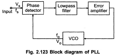
Important Definition of Phase Locked Loop
Important Definition of Phase Locked Loop (PLL): Some Important Definition of Phase Locked Loop PLL are as follows : Lock Range: When PLL is in lock, it can track frequency changes in the incoming signal.…
Comments Off on Important Definition of Phase Locked Loop
September 20, 2016