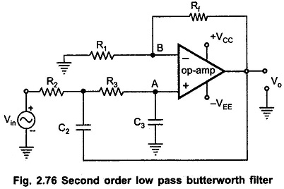
Second Order Low Pass Butterworth Filter
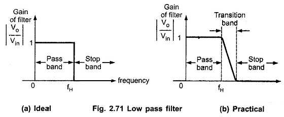
Second Order Low Pass Butterworth Filter: The practical response of Second Order Low Pass Butterworth Filter must be very close to an ideal one. In case of low pass filter, it is always desirable that…
Comments Off on Second Order Low Pass Butterworth Filter
September 8, 2016