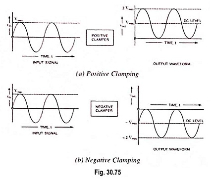
Clamping Circuit Theorem
Clamping Circuit Theorem: Under steady-state conditions, for any input waveform, the shape of the output waveform of a clamping circuit is fixed and also the area in the forward direction and the area in the…
Comments Off on Clamping Circuit Theorem
November 3, 2022