Bandwidth of RLC Circuit:
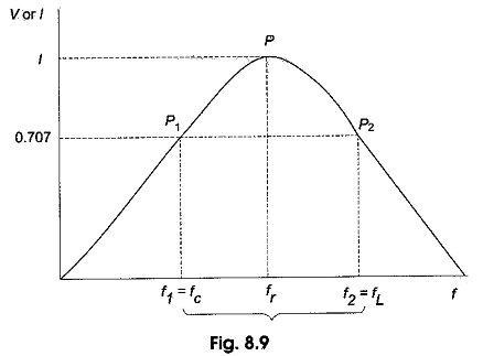
The bandwidth of any system is the range of frequencies for which the current or output voltage is equal to 70.7% of its value at the resonant frequency, and it is denoted by BW. Figure 8.9 shows the response of a series Bandwidth of RLC Circuit.
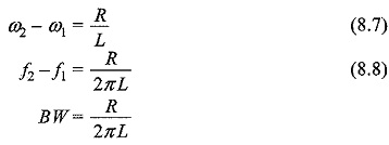
Here the frequency f1 is the frequency at which the current is 0.707 times the current at resonant value, and it is called the lower cut-off frequency. The frequency f2 is the frequency at which the current is 0.707 times the current at resonant value (i.e. maximum value), and is called the upper cut-off frequency. The bandwidth, or BW, is defined as the frequency difference between f2 and f1.
The unit of BW is hertz (Hz).
If the current at P1 is 0.707Imax, the impedance of the Bandwidth of RLC Circuit at this point is √2 R, and hence
Similarly,
If we equate both the above equations, we get
From Eq. 8.3, we get
we have
If we add Eqs 8.1 and 8.2, we get
Since
and
From Eq. 8.6, we have
or
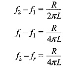
From Eq. 8.9, we have
The lower frequency limit
The upper frequency limit
If we divide the equation on both sides by fr, we get
Here an important property of a coil is defined. It is the ratio of the reactance of the coil to its resistance. This ratio is defined as the Q of the coil. Q is known as a figure of merit, it is also called quality factor and is an indication of the quality of a coil.
If we substitute Eq. (8.11) in Eq. (8.12), we get
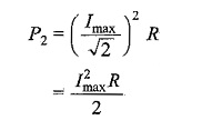
The upper and lower cut-off frequencies are sometimes called the half-power frequencies. At these frequencies the power from the source is half of the power delivered at the resonant frequency.
At resonant frequency, the power is
At frequency f1, the power is
Similarly, at frequency f2, the power is
The response curve in Fig. 8.9 is also called the selectivity curve of the Bandwidth of RLC Circuit. Selectivity indicates how well a resonant circuit responds to a certain frequency and eliminates all other frequencies. The narrower the bandwidth, the greater the selectivity.


