Basic Elements of Static Relay:
The basic elements of a static relay are namely,
Input Element:
Mixing circuits are needed to sum the input signals in a convenient form. Semiconductor circuits are suited to the use of summing junctions, well-known in the analog computing field. Use of operational amplifier as a summer or mixer has already been discussed in an earlier chapter. These input signals are derived from CTs and PTs.
Measuring Element:
This is the most important element as far as Basic Elements of Static Relay operation is concerned since this sends the deciding signal to the output circuit for operation or nonoperation of the relay.
Measuring element may be either (i) single-input device, (ii) two-input device or (iii) multi-input device.
Two-input devices are most common and are basically comparators, which have already been discussed in detail; multi-input devices are the extension of two-input devices to extend the range of complex characteristics.
Special characteristics such as parabolic, elliptical, quadrilateral, etc., can be obtained. A detailed discussion on this will be done at a later stage. Here only single-input device will be considered in brief.
Single-input devices form the basis of many protection and control schemes and may be subdivided as follows.
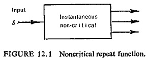
(a) Noncritical Repeat Function (All or Nothing Relay): These are either completely unenergized or energized considerably in excess of marginal conditions, to ensure a fast response with robust contact pressure. In Fig. (12.1), therefore, S is either zero or greater than marginal operation level. Devices of this type are generally instantaneous (20 ms or less) but they may be associated with a time function. They usually involve a switching power gain of 103, and have several outputs, i.e. contacts as shown in Fig. (12.1).
The two main duties of these units in protection are:
- The provision of a final tripping signal to the circuit breaker and possibly supplementary functions of intertripping, alarm and indication.
- acting as intermediate switching stages within an assembly of functional elements, i.e. a protective system.
(b) Critical or Measuring Function: This involves a response to an input when it exceeds a prescribed critical level.
For operation S ≥ A (critical level)
For reset S ≤ KA (K ≤ 1)
Switching gain need not be high as repeat devices can be provided.
Practical requirements are accuracy, long term consistency, fast operation and a controllable reset ratio which should generally be high.
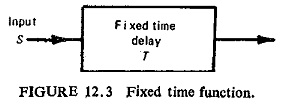
(c) Fixed or Definite Time Function: This function involves a fixed time delay between input and output. The delay may be between the application of an input and the occurrence of the output, or between the removal of the input and the resetting of the output. The input is noncritical, being either nothing or greatly in excess of the critical level. Practical requirements are accuracy of time setting and repeatability under successive energizations.
Practical static timers generally use the controlled charging time of a capacitor, and usually need an auxiliary d.c. supply.
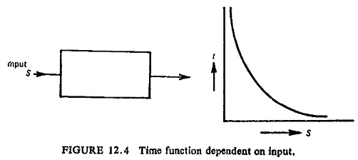
(d) Time Functions Dependent on Input: The commonest form of characteristic is![]()
where n is negative in (Fig. (12.4)).
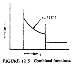
The relays in this category are the inverse definite-minimum-time lag (IDMT) overcurrent and earth-fault relays. The essential feature of such relays is that the operating time is inversely related to some power of the input signal magnitude. It is advantageous to choose a circuit which can accommodate a wide range of alternative inverse time characteristics, precise minimum operating levels, definite minimum times and, where necessary, additional high-set features as shown in Fig. (12.5).
Output Element:
This Basic Elements of Static Relay element amplifies the binary signal, multiplies it and combines it with certain signals and delays it. It processes only binary signals, the quality requirements in relation to the measuring element are much less. This element can be constructed in a much more rugged and less trouble prone form.
Feed Element:
This element provides the d.c. voltage required, for transistors. Alternative means of the d.c. power supply are: (a) potentiometer across the station battery, (b) an auxiliary trickle charged battery and (c) rectification of PT or CT output.


