Logarithmic Amplifier using Diode:
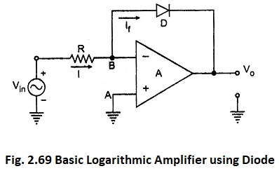
The circuit diagram of basic Logarithmic Amplifier using Diode is shown in the Fig. 2.69.
The diode D is used in the negative feedback path. The node A is grounded hence node B is at virtual ground. Hence VB = 0.
As the op-amp input current is zero,
Now If is the current through diode and voltage across diode is VB – Vo i.e. -Vo.
Hence using equation (10) we can write,
As Io R is constant d.c. voltage, let us denote it as Vref.
Where
- Vref = Io R
Thus the output voltage Vo is a function of logarithm of the input voltage Vin. The Basic Log Amplifier using Diode gives the logarithm to base e i.e., natural logarithm. But the same circuit can be used to find out logarithm values to base 10 by the proper scaling as,


