Capacitance of 3 Core Cables:
The Capacitance of 3 Core Cables is much more important than that of overhead line because in cables
(i) conductors are nearer to each other and to the earthed sheath
(ii) they are separated by a dielectric of permittivity much greater than that of air.
Fig. 11.18 shows a system of capacitances in a 3-core belted cable used for 3-phase system. Since potential difference exists between pairs of conductors and between each conductor and the sheath, electrostatic fields are set up in the cable as shown in Fig. 11.18 (i). These electrostatic fields give rise to core-core capacitances Cc and conductor-earth capacitances Ce as shown in Fig. 11.18 00. The three Cc are delta connected whereas the three Ce are star connected, the sheath forming the star point [See Fig. 11.18 (W)].
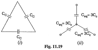
They lay of a belted cable makes it reasonable to assume equality of each Cc and each Ce. The three delta connected capacitances Cc [See Fig. 11.19 (0] can be converted into equivalent star connected Capacitance of 3 Core Cables as shown in Fig. 11.19 (ii). It can be easily shown that equivalent star capacitance Ceq is equal to three times the delta-capacitance Cc i.e. Ceq=3Cc.
The system of Capacitance of 3 Core Cables shown in Fig.11.18
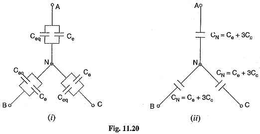
(iii) reduces to the equivalent circuit shown in Fig. 11.20 (i).
Therefore, the whole cable is equivalent to three star-connected capacitors each of Capacitance of 3 Core Cables [See Fig. 11.20 (ii)],
If Vph is the phase voltage, then charging current IC is given by ;
Measurements of Ce and Cc
Although core-core capacitance Cc and core-earth capacitance Ce can be obtained from the empirical formulas for belted cables, their values can also be determined by measurements. For this purpose, the following two measurements are required :
(i) In the first measurement, the three cores are bunched together (i.e. commoned) and the capacitance is measured between the bunched cores and the sheath. The bunching eliminates all the three capacitors Cc, leaving the three capacitors Ce in parallel. Therefore, if C1 is the measured capacitance, this test yields :
Knowing the value of C1, the value of Ce can be determined.
(ii) In the second measurement, two cores are bunched with the sheath and capacitance is measured between them and the third core. This test yields 2Cc + Ce. If C2 is the measured Capacitance of 3 Core Cables, then,
As the value of Ce is known from first test and C2 is found experminentally, therefore, value of Cc can be determined.
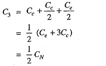
It may be noted here that if value of CN(= Ce+ 3Cc) is desired, it can be found directly by another test. In this test, the capacitance between two cores or lines is measured with the third core free or connected to the sheath. This eliminates one of the capacitors Ce so that if C3 is the measured Capacitance of 3 Core Cables, then,
Current Carrying Capacity of Underground Cables
The safe current-carrying capacity of an underground cable is determined by the maximum permissible temperature rise. The cause of temperature rise is the losses that occur in a cable which appear as heat. These losses are
- Copper losses in the conductors
- Hysteresis losses in the dielectric
- Eddy current losses in the sheath
The safe working conductor temperature is 65°C for armoured cables and 50°C for lead-sheathed cables laid in ducts. The maximum steady temperature conditions prevail when the heat generated in the cable is equal to the heat dissipated. The heat dissipation of the conductor losses is by conduction through the insulation to the sheath from which the total losses (including dielectric and sheath losses) may be conducted to the earth. Therefore, in order to find permissible current loading, the thermal resistivities of the insulation, the protective covering and the soil must be known.


