Capacitance of Single Core Cable:
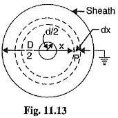
A Capacitance of Single Core Cable can be considered to be equivalent to two long co-axial cylinders. The conductor (or core) of the cable is the inner cylinder while the outer cylinder is represented by lead sheath which is at earth potential. Consider a Capacitance of Single Core Cable with conductor diameter d and inner sheath diameter D (Fig. 11.13). Let the charge per meter axial length of the cable be Q coulombs and e be the permittivity of the insulation material between core and lead sheath. Obviously ε = ε0εr where εr is the relative permittivity of the insulation.
Consider a cylinder of radius x meters and axial length 1 meter. The surface area of this cylinder is =2 π x X 1 = 2 π x m2
Electric flux density at any point P on the considered cylinder is
Electric intensity at point P,
The work done in moving a unit positive charge from point P through a distance dx in the direction of electric field is Ex dx. Hence, the work done in moving a unit positive charge from conductor to sheath, which is the potential difference V between conductor and sheath, is given by :
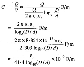
Capacitance of the cable is
If the cable has a length of l meters, then capacitance of the cable is
Dielectric Stress in a Single Core Cable
Under operating conditions, the insulation of a cable is subjected to electrostatic forces. This is known as dielectric stress. The dielectric stress at any point in a cable is infract the potential gradient (or electric intensity) at that point.
Consider a Capacitance of Single Core Cable with core diameter d and internal sheath diameter D. As proved in Art 11.8, the electric intensity at a point x metres from the centre of the cable is
By definition, electric intensity is equal to potential gradient. Therefore, potential gradient g at a point x meters from the centre of cable is
As proved in Art. 11.8, potential difference V between conductor and sheath is
Substituting the value of Q from exp. (ii) in exp. (i), we get,
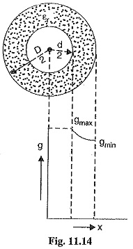
It is clear from exp. (iii) that potential gradient varies inversely as the distance x. Therefore, potential gradient will be maximum when x is minimum i.e., when x = d/2 or at the surface of the conductor. On the other hand, potential gradient will be minimum at x = D/2 or at sheath surface.
Maximum potential gradient is
Minimum potential gradient is
The variation of stress in the dielectric is shown in Fig. 11.14. It is clear that dielectric stress is maximum at the conductor surface and its value goes on decreasing as we move away from the conductor. It may be noted that maximum stress is an important consideration in the design of a cable. For instance, if a cable is to be operated at such a voltage that maximum stress is 5 kV/mm, then the insulation used must have a dielectric strength of at least 5 kV/mm, otherwise breakdown of the cable will become inevitable.
Conductor Size in a Cable
It has already been shown that maximum stress in a cable occurs at the surface of the conductor For safe working of the cable, dielectric strength of the insulation should be more than the maximum stress. Rewriting the expression for maximum stress, we get,
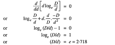
The values of working voltage V and internal sheath diameter D have to be kept fixed at certain values due to design considerations. This leaves conductor diameter d to be the only variable in exp. (i) For given values of V and D, the most economical conductor diameter will be one for which gmax has a minimum value. The value of gmax will be minimum when d loge D/d is maximum i.e.
Most economical conductor diameter is
and the value of gmax under this condition is
For low and medium voltage cables, the value of conductor diameter arrived at by this method (i.e., d = 2 V/gmax) is often too small from the point of view of current density. Therefore, the conductor diameter of such cables is determined from the consideration of safe current density. For high voltage cables, designs based on this theory give a very high value of d, much too large from the point of view of current carrying capacity and it is, therefore, advantageous to increase the conductor diameter to this value. There are three ways of doing this without using excessive copper :
- Using aluminium instead of copper because for the same current, diameter of aluminium will be more than that of copper.
- Using copper wires stranded round a central core of hemp.
- Using a central lead tube instead of hemp.


