CE Circuit with Unbypassed Emitter Resistor:
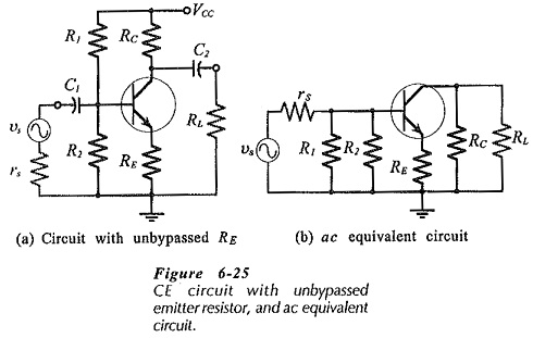
h-parameter Equivalent Circuit – When an CE Circuit with Unbypassed Emitter Resistor (RE) as shown in Fig. 6-25(a), it is also present in the ac equivalent circuit, [Fig. 6-25(b)].
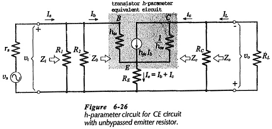
RE must also be shown in the h-parameter circuit between the transistor emitter terminal and the circuit common input-output terminal, (Fig. 6-26). As with the previous h-parameter circuit, the current directions and voltage polarities shown are those that occur when the instantaneous input voltage is positive-going. The presence of RE without a bypass capacitor significantly affects the circuit input impedance and voltage gain.
Input Impedance:
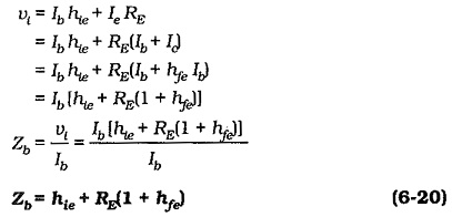
An equation for the input impedance at the transistor base can be determined from υ1 and Ib. From Fig. 6-26,
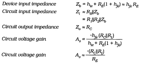
Equation 6-20 gives the input impedance at the transistor base terminal. The circuit input impedance is again given by,
Examination of Eq. 6-20 shows that it is possible to very quickly estimate the input impedance at the transistor base in a CE Circuit with Unbypassed Emitter Resistor. For example, a circuit with RE = 1 kΩ and hfe = 100, has Zb ≈ 100 kΩ.
Output Impedance:
The output impedance at the transistor collector can be shown to be substantially increased (above 1 / hoe) by the presence of the CE Circuit with Unbypassed Emitter Resistor. Consequently, the circuit output impedance should be taken as,![]()
Voltage Gain:
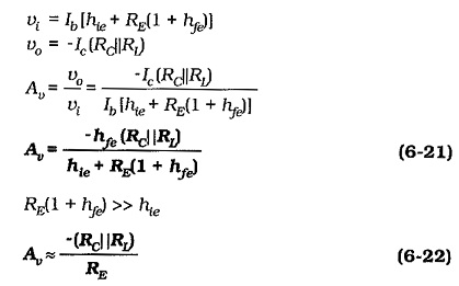
From the derivation of the input impedance equation,
The voltage gain of a CE Circuit with Unbypassed Emitter Resistor can be quickly estimated using Eq. 6-22. For the circuit in Fig. 6-25(a), with RC = 4.7 kΩ, RE =1 kΩ, and RL ≫ RC, Aυ ≈ -4.7.
Performance Summary for CE Circuit with Unbypassed RE
The most significant feature of the performance of a CE Circuit with Unbypassed Emitter Resistor is that its voltage gain is much lower than it would be normally. Its input impedance is also much higher than Zi for a CE circuit that has RE bypassed.
