Characteristics of Synchronous Motor:
Characteristics of Synchronous Motor are constant speed motors. The speed of the motor is decided by the number of poles and frequency. Compared to an induction motor, it is very sensitive to sudden changes of load. This causes a hunting of the rotor and finally leads to stability problems. It has no starting torque and requires starting equipment to bring it to its rated speed. When it is running at its rated speed the field is excited. The damper windings on the field poles help in damping the hunting and providing the starting torque. The motor can be operated at different power factors by changing the excitation. Overexcited synchronous motors operate at leading power factors whereas underexcited ones operate at lagging power factors. They are reasonably efficient. Their efficiency and ability to correct the power factor by varying the excitation make synchronous motors attractive in large power applications. They are preferred as constant speed drives in the industry.
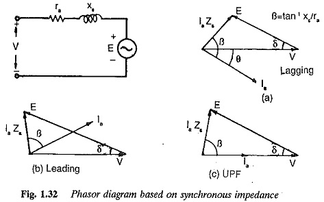
The phasor diagram of a Characteristics of Synchronous Motor is shown in Fig. 1.32. The theory of these motors has been developed on the basis of synchronous reactance, which takes care of leakage reactance and armature reaction. A salient pole machine, which has a non-uniform air gap, is described by direct and quadrature axis reactances. Variation of the armature current of the motor when its excitation is varied is described by V-curves when the motor develops a given power.
The variation of excitation brings about the following:
- change in armature current
- change in line power factor
- slight change in the load angle.
However, there are minimum and maximum excitations for a given power developed.
An increase in the mechanical load at constant excitation would tend to retard the rotor. The angle by which the rotor tends to fall behind the no-load position is called the load angle. In the process of attaining a final position the rotor undergoes oscillations which are damped by damper windings.
Power developed by Characteristics of Synchronous Motor:
The phasor diagram of a cylindrical rotor synchronous motor at a lagging power factor is shown in Fig. 1.32. The power developed by the motor is given by where
where
δ is the load angle
V is the terminal voltage
Et is the induced voltage
The torque developed by the motor is The power developed depends on the excitation. An increase in the excitation results in an increase of Pd. Consequently, the load angle decreases for a given power developed. The overload capacity of the motor increases with an increase in excitation and the machine becomes more stable. If the resistance of the armature is negligible, the power developed is given by
For a salient pole rotor the use of a single synchronous reactance gives unreliable results. The performance of the motor is determined by the use of two reactances, namely direct axis and quadrature axis reactances (Xd, Xq), The former being greater than the latter.
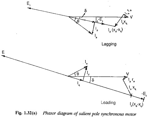
The phasor diagram of an overexcited salient pole synchronous motor is shown in Fig. 1.32(b). Neglecting armature resistance the power developed is given by
When compared with round rotor machines, the following differences are clear:
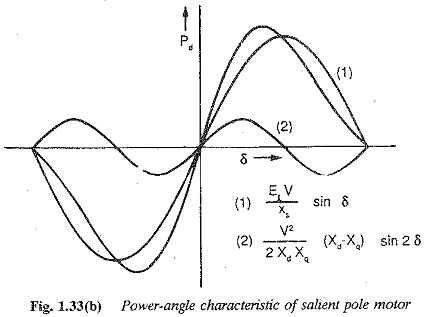
- The power (torque) developed by a salient pole rotor has an additional component due to saliency, which depends upon the difference of the two axes reactances. This is called reluctance power (torque). A salient pole rotor develops more power for a given load angle. This means the power per degree of load angle is greater in a salient pole rotor than that in a round rotor when excitation is the same in both the cases (the two motors are otherwise identical).
- The maximum torque in a salient pole rotor occurs at a torque angle which is less than the corresponding one of a round rotor motor.
- Torque is available in a salient pole rotor even at zero excitation.
Power Angle diagram of Synchronous Motor:
The power angle characteristics of both types of rotor are shown in Fig. 1.33, for different excitations. The torque developed in a synchronous motor is directly proportional to the applied voltage unlike in an induction motors where it is proportional to the square of voltage. Hence it is less sensitive to voltage variations.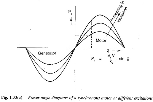
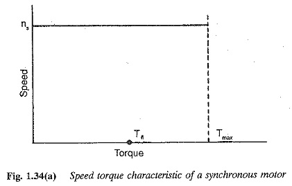
The Torque Speed Characteristics of Synchronous Motor is shown in Fig. 1.34. The characteristic is parallel to the torque axis since the motor is of constant speed type.
The damper windings provided on the pole faces to suppress hunting may also be used to start the motor using the induction motor principle. The
torque speed characteristics of synchronous motor during starting is similar to that of an induction motor, and is depicted in Fig. 1.34 for different damper resistances. To get a better starting torque the damper winding must have a high resistance. However, this inhibits their primary function of damping the os cillations, since a low resistance damper is more effective for this task. A judicious choice of resistance is required, depending upon the application of the motor.
Desirable Modifications to the Torque Speed Curve of Synchronous Motor:
The speed of a Characteristics of Synchronous Motor can be changed only by varying the frequency, i.e. the torque speed characteristics of synchronous motor can be modified only by a variation of the supply frequency. To avoid possible saturation, the voltage is also varied as a function of the frequency. Variable voltage, variable frequency supplies are used to achieve modifications in the speed-torque curve.
Thyristor power converters provide this supply to the motor. Three modes of operation may be identified:
- V ∕ f and E ∕ f constant
- V and E ∕ f constant
- V ∕ f and E constant
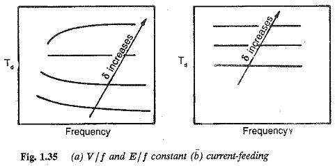
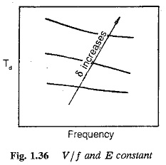
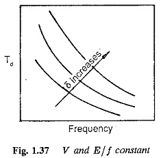
In the first mode of operation the motor operates at constant flux, disregarding the effects of resistance. The current drawn by the motor is independent of stator frequency. Thus speed-torque curves similar to those of a shunt motor are possible. The performance characteristics are shown in Fig. 1.35. In the second mode of operation the motor possesses a series motor characteristic, but the effects of saturation are present. The current drawn at low frequencies is high. The performance characteristics are shown in Fig. 1.36. The third mode of operation gives a mixed performance, as depicted in Fig. 1.37.
Speed Control of Synchronous Motor:
With the availability of thyristor power converters, synchronous motor are becoming increasingly popular as variable speed drives. Two types of control are possible for synchronous motor, when fed from thyristor power converters.
- Separate control
- Self control
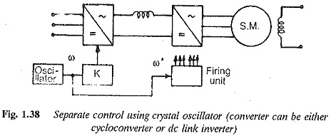
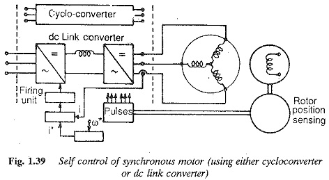
The type of control employed affects both the dynamic and the steady-state performance of the motor. in the former (Fig. 1.38), the motor is fed from a variable frequency supply, the frequency being controlled externally from a crystal oscillator. The motor has the normal synchronous motor operation with all its stability and hunting problems. In self control (Fig. 1.39), the frequency of the input is decided by the rotor speed or stator voltages. A rotor position sensor is used to control the inverter firing pulses. By the time the rotor moves by two pole pitches, all the thyristors in the inverter are fired once in the sequence. Thus the input frequency and rotor speed are related . The firing pluses may be derived by sensing the stator voltages also. With self control the motor has good stability as well as good dynamic performance. The motor acquires dc motor characteristics. The inverter with rotor position sensing or induced voltage sensing is equivalent to a six-segment commutator. A self controlled synchronous motor can replace a dc motor, which has limitations due to its mechanical commutator. In this mode of operation it is also called a commutator-less motor (CLM). The motor may be fed from a VSI or CSI or cycloconverter. When fed from a CSI the motor may be overexcited to make use of the machine voltages for commutation.
The input voltage waveform and current to the Characteristics of Synchronous Motor are non-sinusoidal. The time harmonics of the waveform result in torque pulsations and armature heating. These effects are minimal with a cycloconverter. In the case of CSI feeding, voltage spikes are present. These affect the motor insulation and voltage rating of the inverter.
