Characteristics of Three Phase Induction Motor:
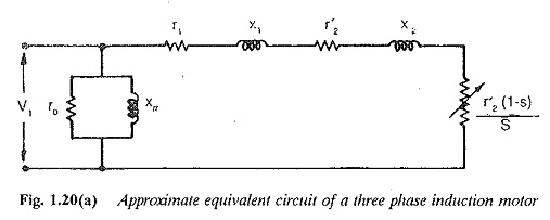
The performance Characteristics of Three Phase Induction Motor can be derived using the approximate equivalent circuit shown in Fig. 1.20(a). In the circuit
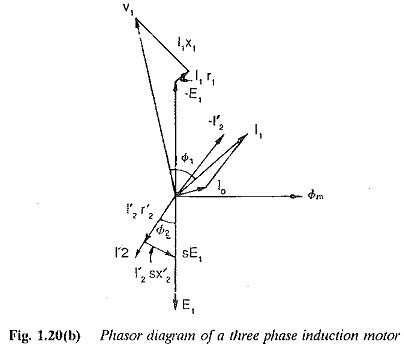
The phasor diagram of the motor is shown in Fig. 1.20(b).
In an induction motor the power transferred to the rotor (Pd), rotor copper loss (Pcu2) and mechanical power developed (Pm) are in the ratio of 1 : s : (1 — s). The torque developed by the motor
But using the relations Pm=Pd(l-s) and nr=ns(l-s) we have
From the equivalent circuit
The torque developed is therefore
At very small slips (operating region of the motor)
and r′2/s≫r1 leading to
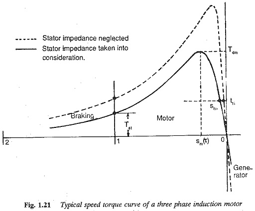
This shows that the torque developed is directly proportional to the slip. In a similar way, at large slips the torque varies in inverse proportion to the slip. At intermediate slips the torque developed needs to be calculated. The speed (slip) torque characteristic is shown in Fig. 1.21.
From the trend of the characteristic it can be seen that there is a maximum value for the torque. The slip at which this maximum torque occurs is given by
The maximum torque is
Sometimes the stator impedance is neglected or the stator impedance drop is compensated to operate the motor at constant flux at all slips. The applied voltage is increased such that the induced voltage. E1/f is constant (equal to the value at rated voltage). The applied voltage varies as a function of frequency such that E1/f remains constant. The stator impedance can be assumed to be zero since it has no effect. In such a case the relations are
‘The speed-torque curve for this case is also shown in Fig. 1.21.
Note the following features of a typical speed-torque curve (Fig. 1.21):
- At exactly synchronous speed s = 0 the torque developed is zero (Td = 0). This can be expected because there are no induced currents due to zero relative speed.
- Full load torque corresponds to the rated slip.
- Tdm is the maximum torque at the slip Sm(T)
- Tst is the starting torque at s = 1.
The torque developed at any slip s expressed as a fraction of maximum torque is given by
where a=r1/r′2. When the stator resistance r1 is neglected
The operation of the motor in the range of slips 0 – sm is stable. When the motor is operating in this range any disturbance in the operating point by change of either speed or torque is damped out and the motor returns to its original operating point or attains a new one. For stable operation the torque developed must increase when the speed falls, i.e.,
The operation of the motor in the range sm. to / is unstable. In this range the curve has a positive dTd/dns, i.e. torque decreases when speed falls.
The characteristic is almost linear at very small slips (in the stable operating region). This linearity continues till the break down torque point for the case of operation with constant flux. The characteristics shown in Fig. 1.21 are redrawn in the same figure.
For slips greater than unity, the operation is in the fourth quadrant. The rotation of the rotor and the rotating magnetic field are in opposite direction. The torque developed is a braking torque, tending to stop the motor. This can occur in two ways:
- The phase sequence of the supply to the motor is reversed while it is running.
- A negative torque is applied to the shaft.
The motor is operated as a brake in the range of slips (s > 1) to make it drive the load at constant speed while lowering the load. The torque is positive, whereas the direction of rotation is reversed. By a suitable resistance of the rotor the point of operation is shifted to the quadrant of operation so that the load is lowered at constant speed.
The torque-speed curve extends to the second quadrant, representing a negative torque in the forward direction of rotation. This occurs if the speed of
the rotor is greater than the synchronous speed. Any tendency of the rotor to accelerate beyond synchronous speed is arrested by a generating torque. In this mode of operation all the kinetic energy connected with increase in speed is returned to the mains. The maximum (break down) torque depends on the following:
- It varies as the square of the applied voltage.
- It decreases with stator impedance.
- Its value is independent of the rotor resistance.
- Its value decreases with an increase in the rotor leakage reactance.


