Choke Balun:
A Choke Balun, or balance-to-unbalance transformer, is a circuit element used to connect a balanced line to an unbalanced line or antenna. Or, as is perhaps a little more common, it is used to connect an unbalanced (coaxial) line to a balanced antenna such as a dipole. At frequencies low enough for this to be possible, an ordinary tuned transformer is employed. This has an unbalanced primary and a center-tapped secondary winding, to which the balanced antenna is connected. It must also have an electrostatic shield, which is earthed to minimise the effects of stray capacitance.
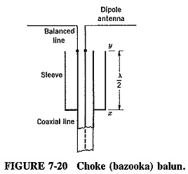
For higher frequencies, several transmission-line Choke Balun exist for differing purposes and narrow-band or broadband applications. The most common balun, a narrow-band one, will be described here, as shown in cross section in Figure 7-20. It is known as the Choke Balun, sleeve, or bazooka balun.
As shown, a quarter-wavelength sleeve is placed around the outer conductor of the coaxial line and is connected to it at x. At the point y, therefore, λ/4 away from x, the impedance seen when looking down into the transmission line formed of the sleeve and the outer conductor of the coaxial line is infinite. The outer conductor of the coaxial line no longer has zero impedance to ground at y. One of the wires of the balanced line may be connected to it without fear of being short-circuited to ground. The other balanced wire is connected to the inner conductor of the coaxial line. Any balanced load, such as the simple dipole antenna shown in Figure 7-20, may now be placed upon it.
The Slotted Line:
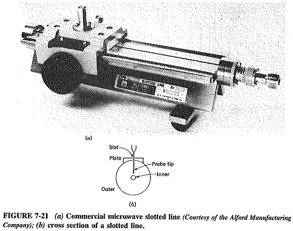
It can be appreciated that a piece of transmission line, so constructed that the voltage or current along it can be measured continuously over its length, would be of real use in a lot of measurement situations. At relatively low frequencies, say up to about 100 MHz, a pair of parallel-wire lines may be used, having a travelling detector connected between them. This detector is easily movable and has facilities for determining the distance of the probe from either end of the line. The Lecher line is the name given to this piece of equipment, whose high-frequency equivalent is the slotted line, as shown in Figure 7-21.
The slotted line is a piece of coaxial line with a long narrow longitudinal slot in the outer conductor. A flat plate is mounted on the outer conductor, with a corresponding slot in it to carry the detector probe carriage. It has a rule on the side, with a vernier for microwave frequencies to indicate the exact position of the probe. The probe extends into the slot, coming quite close to the inner conductor of the line, but not touching it, as shown in Figure 7-21b. In this fashion, loose coupling between line and probe is obtained which is adequate for measurements, but small enough so as not to interfere unduly.
The scoffed line must have the same characteristic impedance as the main line to which it is connected in series. It must also have a length somewhat in excess of a half-wavelength at the lowest frequency of operation.
The slotted line simply permits convenient and accurate measurement of the position and size of the first voltage maximum from the load, and any subsequent Ones as may be desired, without interfering significantly with the quantities being measured.
The knowledge of these quantities permits calculation of
- Load impedance
- Standing-wave ratio
- Frequency of the generator being used
The practical measurement and calculations methods are normally indicated in the instructions that come with a particular slotted line. Measurement methods for these parameters that do not involve the slotted line also exist.

