Chopper Fed DC Drives:
The variable voltage to the armature of a dc motor for speed control can be obtained from a dc chopper which is a single stage dc to dc conversion device. The voltage variation at the load terminals can be obtained by using either current limit control or time ratio control. In the former, as has already been discussed, the chopper is controlled such that the load current has a variation between two limits. When the current reaches the upper limit the chopper is turned off to disconnect the motor from the supply. The load current freewheels through freewheeling diode and decays. When it falls to the lower limit the chopper is turned on, connecting the motor to the supply. An average current is always maintained. When the chopper is controlled by TRC the ratio of TON/TOFF of the chopper is changed. In this case the operation is at fixed frequency if (TON+TOFF) is kept constant. TON only is varied to obtain voltage control. The operation will be at variable frequency with TON kept constant and (TON+TOFF) varied. But owing to several advantages of simplicity, a fixed frequency TRC is normally used. Chopper circuits are used to control both separately excited and series motors.
Chopper circuits have several advantages over phase controlled converters:
1.Ripple content in the output is small. Peak/average and rms/average current ratios are small. This improves the commutation and decreases the harmonic heating of the motor. The pulsating torques are also less.
2.The chopper is supplied from a constant de voltage using batteries. The problem of power factor does not occur at all. The conventional phase control method suffers from a poorer power factor as the angle is delayed. This means that the current drawn by the chopper is smaller than in a ac/dc phase controlled converter.
3.The circuit is simpe and can be modified to provide regeneration.
4.The control circuit is simple.
However, because of the forced commutation employed, the chopper may be costlier than a phase controlled converter.
Chopper Drives using TRC
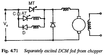
Separately excited dc motor : A separately excited dc motor fed from a dc chopper employing TRC strategy is shown in Fig. 4.71. The variation of time ratio at constant chopper frequency provides a variable voltage. The load current can be determined using the relevant equations. During ON period the current in the load grows and in the OFF period the current decays. The current waveform is shown in Fig. 4.72. Due to back emf present in the circuit the variation of currents is almost linear. A detailed study of the drive on TRC strategy shows that the motor has the following features:
A combination of constant frequency and variable TRC strategies gives a better performance. The question of power factor does not occur when the chopper is fed from a constant voltage source such as batteries. Sometimes the dc voltage is obtained from a diode rectifier. In this case the power factor on the ac side is better than that in phase control. But regeneration is not possible in this case, whereas it is possible when fed from batteries.
At very low frequencies of operation and smaller time ratios the load current may become discontinuous. The output ripple depends on TR. At low currents the ripple becomes responsible for discontinuous operation. At very light loads if the average current is smaller than 1/2 (peak to peak) of the ripple amplitude, the load current becomes discontinuous, as shown in Fig. 4.73. Discontinuous conduction occurs if the freewheeling period is larger. In other words, ON time is less than a critical value. As far as the discontinuous conduction is concerned, choppers are similar to ac/dc converters. The peak current cannot be controlled. The limits between which the current varies depends upon TR. The peak current and discontinuous conduction affect the commutation capability of the motor and its speed control range. However the operation of the motor on chopper is better than that on ac/dc converters. In the case of a dc motor fed from a chopper the discontinuous conduction can be eliminated by increasing chopper frequency or by adding extra inductance in the armature circuit. The amount of inductance is rather small.
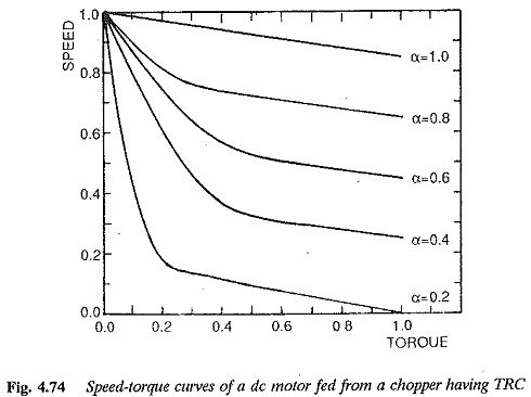
The torque-speed characteristic is drooping in nature. The speed regulation of the motor is better with chopper control than with the phase angle control. The speed-torque characteristic is essentially the same at all time ratios, (Fig. 4.74).
The ratios of peak/average and rms/average current depend upon 1R and hence speed. Therefore the chopper control shows improved performance at high speed. The performance can be improved by an inductance in the armature circuit. The peak current can be significantly reduced so that the commutating capability increases, The heating of the motor will be less. Multi quadrant operation is possible.
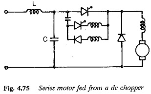
Series Motor : Series motors produce high starting torque. They are capable of constant power operation at all speeds. They are therefore suitable for traction purposes. Choppers are used to control these motors. Both the control strategies of TRC and CLC are used. The schematic of a series motor fed from a chopper operating with fixed frequency variable TR is shown in Fig. 4.75.
As in the case of separately excited dc motor, the current drawn by the motor is smaller than that of PAC. When a battery is used to supply the chopper, regeneration is possible and power factor does not pose a problem. However when the dc voltage is provided by means of diode rectifier, regeneration is not possible and the power factor is better than that of a phase controlled rectifier.
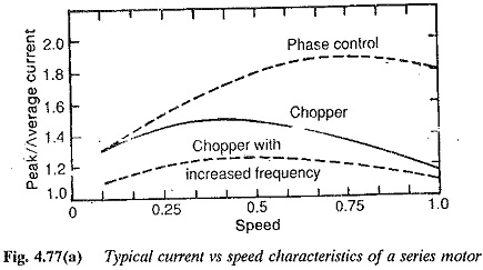
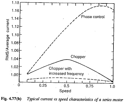
The ratios of peak/average and rms/average are functions of the time ratio. As compared to phase controlled converters, these are considerably smaller in chopper control. Chopper control improves the performance, the improvement being more at high chopping frequencies.
The discontinuous conduction takes place at very small current ratios. As has already been discussed previously, the series motor is less prone to discontinuous conduction than a separately excited motor. This is because the back emf in a series motor is a function of armature current. Also the speed control range of a chopper fed motor is better than that of the motor fed from a phase controlled rectifier. The discontinuous conduction can be eliminated by means of a proper armature inductance. The ripple content gets reduced, which decreases the possibility of discontinuous conduction. High chopper frequency helps in eliminating the discontinuous conduction in the load at small time ratios.
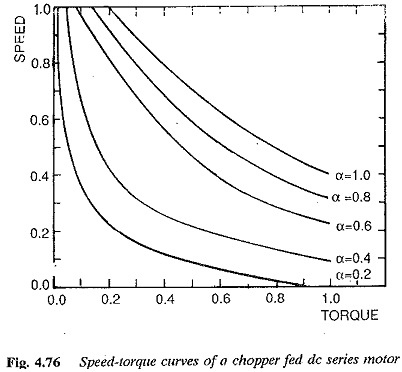
Typical torque-speed characteristics of a series motor for different time ratios are shown in Fig. 4.76. The speed control range is affected only at small time ratios. As the time ratio increases the characteristic moves towards the left and the range of speed control also increases.
The armature current pulsations may cause armature heating. However, this is smaller compared to the operation of motors with phase control.
As the speed increases the average current drawn decreases. A typical current versus speed characteristic is shown in Fig. 4.77. This can be expected in a series motor as the field current is the same as the armature current. At small time ratios and low armature current there is a possibility for discontinuous conduction. So high speeds may not be possible at small time ratios, as is evident from Fig. 4.76. Because of saturation very low speeds are not possible. As the time ratio increases the lower limit on the speed also increases. At smaller time ratios higher speeds are not possible and at larger time ratios lower speeds are not possible.
Regeneration is possible using a two quadrant chopper circuit. A stable series generator operation is possible using a chopper circuit.
The peak currents also depend upon the time ratio and affect the commutating capability. The commutating capability of a chopper fed motor is better than that of a motor fed from a phase controlled converter.
The above discussion shows that the motor performance is better at high chopper frequencies. But when the time of commutation becomes comparable to the ON time of the chopper, it introduces a voltage regulation. The switching losses are more.
A chopper fed series motor is preferable to a series motor fed from a phase controlled converter because of improved performance.
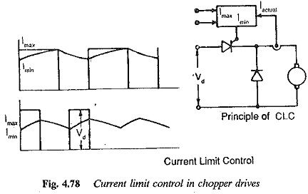
Chopper drives with CLC : The current limit control used with phase controlled rectifiers can be used with choppers also. A schematic of a motor fed from a chopper employing CLC is shown in Fig. 4.78. CLC gives better performance compared to TRC. This is because of the defined current limits. The peak current is under control. The commutation capability increases. The ripple content is controlled by making the difference between the current limits small. The motor heating it less, but the chopper frequency increases, introducing losses and voltage regulation due to commutation. The speed-torque characteristic is improved. At high currents the lowest speed is limited due to saturation. At lower currents there is the possibility of discontinuous conduction only if the ripple is high. By proper control we can completely eliminate the discontinuous conduction. These advantages are available with both series and separately excited dc motors.
