Circuit Constants of a Transmission Line:
In any four terminal network, the input voltage and input current can be expressed in terms of output voltage and output current. Incidentally, a Circuit Constants of a Transmission Line is a 4-terminal network ; two input terminals where power enters the network and two output terminals where power leaves the network.
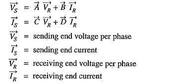
Therefore, the input voltage (VS) and input current (IS) of a 3-phase Circuit Constants of a Transmission Line can be expressed as :
and A,B,C and D (generally complex numbers) are the constants, known as generalised circuit constants of the transmission line. The values of these constants depend upon the particular method adopted for solving a Circuit Constants of a Transmission Line. Once the values of these constants are known, performance calculations of the line can be easily worked out. The following points may be kept in mind :
- The constants A,B,C and D are generally complex numbers.
- The constants A and D are dimensionless whereas the dimensions of B and C are ohms and siemen respectively.
- For a given transmission line,
- For a given transmission line,
We shall establish the correctness of above characteristics of generalised circuit constants in the following discussion.
Determination of Generalised Constants for Transmission Lines:
As stated previously, the sending end voltage (VS) and sending end current (IS) of a transmission line can be expressed as :
We shall now determine the values of these constants for different types of transmission.lines.
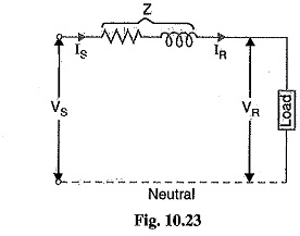
(i) Short lines: In short transmission lines, the effect of line capacitance is neglected. Therefore, the line is considered to have series impedance. Fig. 10.23 shows the circuit of a 3-phase Circuit Constants of a Transmission Line on a single phase basis.
Comparing these with eqs, (i) and (ii), we have,
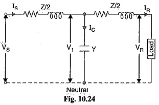
(ii) Medium lines — Nominal T method. In this method, the whole line to neutral capacitance is assumed to be concentrated at the middle point of the line and half the line resistance and reactance are lumped on either side as shown in Fig. 10.24.

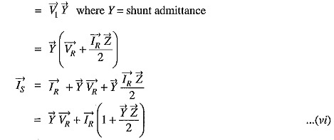 Substituting the value of V1 in eq. (v), we get,
 Substituing the value of IS, we get,
 Comparing eqs. (vii) and (vi) with those of (i) and (ii), we have,
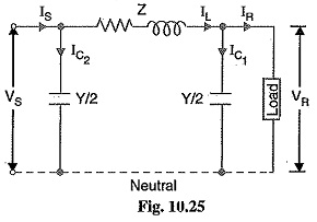
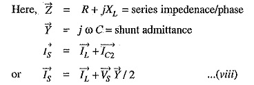
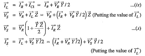
 (iii) Medium lines—Nominal π method. In this method, line-to-neutral capacitance is divided into two halves ; one half being concentrated at the load end and the other half at the sending end as shown in Fig. 10.25.
Putting the value of VS from eq. (x), we get,
Comparing equations (x) and (xi) with those of (i) and (ii), we get,
(iv) Long lines—Rigorous method. By rigorous method, the sending end voltage and current of a long Circuit Constants of a Transmission Line are given by :
Comparing these equations with those of (i) and (ii), we get,
