Classification of Relays:
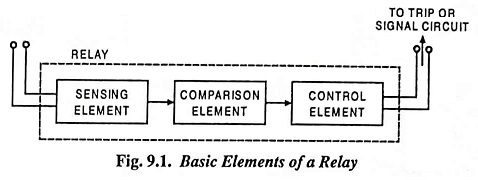
The protective relay may be defined as an electrical device interposed between the main circuit and the circuit breaker in such a manner that any abnormality in the circuit acts on the relay, which in turn, if the abnormality is of a dangerous character, causes the breaker to open and so to isolate the faulty clement. The relay ensures the safety of the circuit equipment from any damage which might be otherwise caused by the fault. Classification of Relays have three essential fundamental elements, as illustrated in Fig. 9.1.
- Sensing element, sometimes also called the measuring element, responds to the change in the actuating quantity, the current in a protected system in case of overcurrent relay.
- Comparing element serves to compare the action of the actuating quantity on the relay with a preselected relay setting.
- Control element on a pick up of the relay, accomplishes a sudden change in the control quantity such as closing of the operative current circuit.
Classification of Relays as to which kind of physical quantity the sensing element respond to and may be classed as electrical (actuated by some electrical quantity such as current, voltage, power etc.); mechanical (actuated by pressure, velocity of outflow of a liquid or gas etc.), thermal (actuated by heating effect), optical, acoustical, and other types of relays.
In power system protective relaying, the most widely applied are electrical type relays. Generally speaking the classification of relays in electrical protective relays can be divided into two categories: (i) electromagnetic relays and (ii) static relays.
According to principle of operation and construction, the classification of relays are electromagnetic attraction type, electromagnetic induction type, electrodynamic type, moving coil type, electro-thermal type, physicoelectric type and static relays.
Electromagnetic attraction relays are of two types namely attracted armature type and solenoid type. In an attracted armature type relay operation depends on the movement of an armature under the influence of attractive force due to magnetic field set up by the current flowing through the relay winding while in a solenoid type relay operation depends on the movement of an iron plunger core along the axis of solenoid. Moving iron, moving plunger, attracted armature hinged, and balanced beam types of relays fall under this category. Such relays are actuated by dc or ac quantities.
In an electromagnetic induction type relay operation depends on the movement of a metallic disc or cylinder free to rotate by the interaction of induced currents and the alternating magnetic fields producing them.
In an electrodynamic type relay moving member consists of a coil free to rotate in an electromagnetic field as in case of a moving coil instrument.
In a moving coil type relay moving member consists of a coil free to rotate in the air gap of a permanent magnet.
In an electro-thermal type relay movement depends up on the action of heat produced by the current flowing through the element of the relay.
Buchholz relay is an example of physicoelectric relay.
According to their functions in the relay protective scheme, relays may be divided into main, auxiliary (or supplementary) and signal relays. The main relays are the protective elements which respond to any change in the actuating quantity. e.g., current, voltage, power etc. The auxiliary or supplementary relays are those which are controlled by other relays to perform some auxiliary or supplementary function such as introduction of a time delay, multiplying the number of contacts, increasing the making or breaking capacity of the contacts of another relay, passing a command pulse from one relay to another relay, acting upon a circuit breaker closing or opening coil, energizing a signal or an alarm, etc. Signal relays function to register (by flag or target) the operation of some relay or relay protection, and control warning (visible) and alarm (audible) signal devices. The choice of signal relay is governed by the importance of the associated switchgear, the method of control and the number of alarm indications to be displayed.
According to actuating quantity, electrical relays are classified into current, voltage, power, reactance, impedance, frequency relays, and, according to the direction of the change they respond to, as minimum (or under) and maximum (over) relays. A maximum (or over) relay is one which responds to the actuating quantity when it exceeds a predetermined value as in the case of an overcurrent relay which operates when the current exceeds a predetermined value. A minimum (or under) relay is one which operates when the value of actuating quantity drops below a predetermined value as in case of an undervoltage relay which operates when the voltage falls below a particular level.
According to the connection of sensing element, relays are classed as primary and secondary relays. Primary relays are those whose sensing (or measuring) elements are directly connected in the circuit or element they protect, while the secondary relays are those whose measuring elements are connected to the circuit they protect through instrument transformers (CTs or PTs). Normally secondary relays are used in power system protection because of the high values of line voltages and currents.
As to how the relays act upon the circuit breaker, they are subdivided into direct-acting relay whose control element acts mechanically to operate a circuit breaker and indirect-acting relay whose control element operates an auxiliary (operative) power source circuit to control the circuit breaker.
Primary relays, despite the substantial simplification of the protective schemes afforded by them are employed only in the simplest schemes for low-voltage circuits. The application of primary relays to high-voltage circuits is rendered difficult by complications arising from their conditions of operation and servicing (adjustment, checking, supervision at the high voltage). Protective schemes using indirect-acting primary relays need, furthermore, the use of an operative current. Such arrangements are bulky and costly. Direct-acting secondary relays do not require an operative current, their armatures act directly upon the circuit breaker tripping device. Protection schemes using direct-acting secondary relays, notwithstanding difficulty in checking and adjustment, have found application because of their simple design.
The relay most frequently used is the indirect-acting secondary relay, notwithstanding the greater complexity of the protection scheme and the need for operative power. Such relays allow changes to be made in their settings and can be removed, or cut out of the circuit for repair or checking during operation of the circuit element they protect. Such relays, furthermore, possess a relatively high sensitivity and, due to the fact that the connections to the protected circuit elements are made through instrument transformers, are electrically isolated from the high primary circuit voltage. They are also to a much lesser degree than primary relays subject to the action of short-circuit currents.
As to time of action relays can be distinguished as relays without time delay and relays with time delay. Among the relays which fall under the category of non-time delay are non-inertia types with operating times of several thousandths of a second (milliseconds)—usually electronic relays; quick-acting relays with operating times ranging from 5 to 40 ms, and ordinary relays with operating times of 0.04 to 0.2 second. Among the time delay or time lag relays are relays with non-regulable time delay, obtained mainly by the use of short-circuited windings, eddy current sleeves etc., and also relays with regulable time delay. The latter type is termed time lag relays. Protective relay schemes use time lag relays having time delays ranging from about 0.2 s up to 5 to 20 s.
As to type of contacts, relays can be differentiated as relays with normally-open (n-o) and normally-closed (n–c) contacts. The relay contacts are called normally-open (n-o) if they are open (separated) when the relay winding is not energised, and normally-closed (n-c) if they are closed (in contact) when the relay winding is not energised. Use is also made of relays provided with two-way or double-throw contacts and with sliding contacts (which during relay operation close for a brief interval of time). When relays are operated, their contacts may close or open instantaneously or with time delay. Relay contacts, depending upon the type and function of the relay, as well as type and material of the contacts themselves, are capable of satisfactorily withstanding multitudes of operations in operative circuits of the corresponding voltage (usually 12 to 220 V) and switch circuits handling power flows ranging from several to hundreds of volt-amperes (VA).
According to applications, the Classification of Relays as :
- Overvoltage, Overcurrent and Overpower Relay: The relay operates when the voltage, current or power rises above a specified value.
- Undervoltage, Undercurrent and Underpower Relay: The relay operates when the voltage, current or power falls below a specified value.
- Directional or Reverse Current Relay: The relay operates when the applied current assumes a specified phase displacement with respect to the applied voltage and the relay is compensated for fall in voltage.
- Directional or Reverse Power Relay: The relay operates when the applied current and voltage assume specified phase displacement and no compensation is allowed for fall in voltage.
- Differential Relay: The relay operates when some specified phase or magnitude difference between two or more electrical quantities occurs.
- Distance Relay: In this relay the operation depends upon the ratio of the voltage to the current.
According to timing characteristics the classification of relays are :
- Instantaneous Relays: In these relays complete operation takes place after a very short (negligible) time duration from the incidence of the current or other quantity resulting in operation. The time of operation of such relays is lesser than 0.2 second.
- Definite Time Lag Relays: In these relays the time of operation is sensibly independent of the magnitude of the current or of other quantity causing operation.
- Inverse Time Lag Relays: In these relays the time of operation is approximately inversely proportional to the magnitude of the current or other quantity causing operation.
- Inverse Definite Minimum Time (IDMT) Lag Relays: In these relays the time of operation is approximately inversely proportional to the smaller values of current or other quantity causing operation and tends to be a definite minimum time as the value increases without limit.
In induction type of relays the time lag may be achieved by employing a permanent magnet which is so arranged that the relay rotor cuts the flux between the poles of this magnet. Such a magnet is called the “drag magnet“.
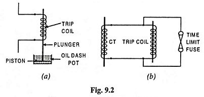
In other types of relays this may be achieved in two ways. Firstly, when a series connected overload trip coil is used, an oil dash pot can be attached in which is a piston connected to the lower end of the solenoid plunger of the relay. In case of fault when the plunger is pulled, the piston, immersed in the oil, retards plunger motion, thus provides the necessary drag or delay in the relay operation, as shown in Fig. 9.2 (a).
When the trip coil is transformer operated, time delay is achieved by connecting a time-limit fuse across the trip coil i.e., in parallel. This fuse should have an inverse time-current characteristic and will normally carry the CT secondary current to bypass the trip coil. As and when sufficient current occurs to “blow” this fuse, the whole current is then transferred to the trip coil which operates to trip the circuit breaker. This is illustrated in Fig. 9.2 (b).

