CMOS NOR Gate Circuit:
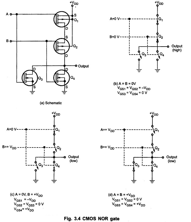
Fig. 3.4 shows 2-input CMOS NOR Gate Circuit. Here, P-channel MOSFETs Q1 and Q2 are connected in series and N-channel MOSFETs Q3 and Q4 are connected in parallel.
Like NAND circuit, this circuit can be analyzed by realizing that a LOW at any input turns ON its corresponding P-channel MOSFET and turns OFF its corresponding N-channel MOSFET, and vice versa for a HIGH input. This is illustrated in Fig. 3.4.
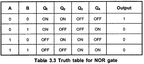
The Table 3.3 summarizes the operation of 2 Input NOR Gate.

